No. 99 Yilan Rd., Xiamen , CN.
+86 186 5928 0806

Arc Beams Fabrication for Underwater Wreck Salvage Devices

1 Project Background

A sunken ancient ship lies beneath the seabed at the mouth of a sea, covered entirely by underwater sediment. To carry out the conservation and archaeological work of the ancient ship, it is necessary to protect the entire ship and its various artifacts completely. Therefore, in the process of salvaging the entire sunken ship, a non-contact method is employed to salvage the ancient ship as a whole to prevent damage. As a key salvaging device throughout the entire process, this apparatus is mainly composed of components such as side end plates, a top beam, a starting frame, and an arc beam, as illustrated in Figure 1.

Schematic structure of the underwater sunken ship salvaging device

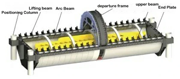
Figure 1 Schematic structure of the underwater sunken ship salvaging device

During the salvaging process, the arc beam components are pre-installed inside the launching frame. The electric motor in the starting frame drives the gear, propelling the arc beam to rotate around the center of the launching frame in a circular motion along the arc rack and the arc roller surface. Several arc beams are connected to form a whole, enveloping the entire sunken ship. The connecting structure between the arc beams is illustrated in Figure 2. Finally, using a lifting beam, all the arc beams, along with the sunken ship, are lifted out of the water.

Schematic of the arc beam connection structure

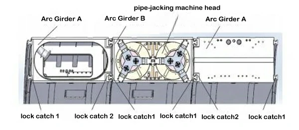
Figure 2 Schematic of the arc beam connection structure

2 Introduction to Arc Beam Components

The arc beam components are large welded steel structures made of Q355B material, forming a semi-circular structure with a diameter of approximately 20 meters. The cross-section of the arc beam is a rectangular frame structure with outer dimensions of about 1m × 2m. The device comprises over 20 arc beams of the same size and specifications. The structure of the arc beam components is shown in Figure 3.
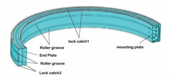
structure of the arc beam components

Figure 3

3 Precision Requirements for Manufacturing

To ensure the smooth operation of the entire arc beam, there are high precision requirements for the manufacturing of the arc beam. After welding, the dimensional tolerances and geometric tolerances of the inner and outer arcs, as well as the upper and lower planes, must be controlled within ±5mm. After mechanical processing, the arc diameter size accuracy of the inner and outer arc roller grooves and the distance size accuracy between the upper and lower plane arc plate male and female locking slot surfaces must be controlled within ±0.4mm. The perpendicularity tolerance between the male and female locking slot mounting surface of the upper and lower plane arc plates and the roller guide groove mounting surface of the inner and outer arc plates must be controlled within ±0.4mm. The coaxiality of the upper and lower arc roller groove mounting surfaces of the inner and outer arcs must be controlled within ±0.4mm.

4 Welding Fixtures and Welding Process

(1) Welding Fixtures
In order to meet the welding precision requirements of the core arc beam component of the salvaging device, reduce welding deformation, and ensure that the machining allowance on the welding structure of the arc beam is small and uniform for easy subsequent mechanical processing of the mating installation surfaces, the dimensional accuracy of each arc beam, especially the roundness of the arc surface after welding, is controlled within ±5mm. A dedicated welding clamping and positioning fixture for arc beam components has been designed

Overview of Welding Fixture:

A reference point is set on the horizontal ground, a central axis is established perpendicular to the ground, serving as the measurement reference point for the welding fixture of the salvaging device's arc beam. The fixture and parts are oriented with one side near the central axis as the inner side and the opposite side as the outer side. Multiple radial support beams are laid out radially with the central axis as the center, with some instances having 8 radial support beams arranged at equal intervals to form a semi-circle. The radial support beams are arranged in two layers, including bottom radial support beams and top radial support beams. Longitudinal support beams and inclined reinforcing ribs connect the bottom radial support beams, and the top radial support beams provide longitudinal support. Inner and outer positioning blocks are set on the radial support beams. The bottom inner positioning block and bottom outer positioning block are set on the bottom radial support beam, while the top inner positioning block and top outer positioning block are set on the top radial support beam. The outer end face of the bottom inner positioning block and top inner positioning block is at a distance from the central axis equal to the radius of the inner arc surface of the arc beam. The inner end face of the bottom outer positioning block and top outer positioning block is at a distance from the central axis equal to the radius of the outer surface of the outer arc plate of the arc beam. The above errors are controlled within a range of 0.5mm.

(2) Welding Process
The welding process is described as follows:

  1. Use laser cutting equipment to cut the plates, process the sub-parts of the bottom arc plate, inner arc plate, outer arc plate, upper arc plate, and internal reinforcing rib plate. The dimensional accuracy is controlled within 0.5mm. Use a rolling machine for rolling processing, with the arc roundness controlled within 3mm.
  2. Successively hoist the sub-parts of the bottom arc plate, inner arc plate, outer arc plate, upper arc plate, and internal reinforcing rib plate onto the bottom radial support beam. After spot welding each part in place, use a three-dimensional laser detector to recheck the arc accuracy. In specific implementations, hydraulic jacks are used for mechanical correction or flame correction is applied to eliminate dimensional errors.
  3. In specific implementations, control and verify the flatness of the bottom arc plate and upper arc plate. During the hoisting and welding of the sub-parts of the bottom arc plate and upper arc plate, a three-dimensional laser detector and a level are used for flatness rechecks. Dimensional correction is performed for areas where the flatness exceeds 1mm.
  4. Before warehousing, use a three-dimensional laser detector and a level for the final re-measurement of the arc accuracy and flatness of the entire arc beam.

5. Machining Clamping and Positioning Fixture

To address the manufacturing precision requirements and the issue of batch processing for the core arc beam components of the salvaging device, a set of machining clamping and positioning fixtures for the arc beam components has been specially designed, as shown in Figure 4. The main structural features of the clamping and positioning fixture are described below.

Arc Beam Clamping Form

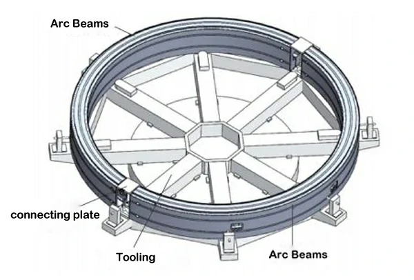
Figure 4 Arc Beam Clamping Form

  1. For machining the arc beam, a vertical lathe with a rotating diameter of up to 20m is used, with a table diameter of 10m and a tool holder travel of 9.5m. Eight radial support beams, each with a length of 11m, are arranged radially along the radial direction with the table's rotating center as the reference point. These support beams extend out from the work table and are connected by outer and inner ring connecting beams, forming a whole that can clamp two arc beams at once. This ensures the rigidity of the machining fixture.
  2. At the upper part of the radial support beams, there are inner arc surface positioning bosses and outer arc surface positioning bosses, making the rotating centers of the arc beam part, the inner arc surface positioning boss, and the outer arc surface positioning boss concentric. The distance from the inner arc surface positioning boss to the rotating center of the work table is equal to the radius value of the inner arc of the arc beam's male-female lock groove, and the distance from the outer arc surface positioning boss to the rotating center of the work table is equal to the radius value of the outer arc of the arc beam's male-female lock groove.
  3. At the upper part of the radial support beams, a radial clamp is installed on one side of the inner arc surface of the arc beam. The radial clamp can not only extend and retract but can also radially clamp and release the arc beam. A top measuring fixture is also installed on one side of the outer arc surface of the arc beam, and it can extend and retract as well as radially clamp and release the arc beam. Additionally, two hydraulic jacks are placed in the middle position between the inner and outer arc surface positioning bosses, allowing adjustment of the height position of the arc beam.

6. Machining Process

The machining process for the arc beam components is described as follows:

  1. Suspend the arc beam fixture on the worktable of a vertical lathe with a machining diameter of up to 20m, install and debug it, tighten the T-shaped clamping bolts on the worktable, and secure the arc beam fixture.
  2. On the machine tool, turn and machine the inner and outer arc surface positioning bosses on the fixture. The distances from the inner and outer arc surface positioning bosses on the fixture to the center of rotation are equal to the radius values of the inner and outer arc surfaces of the arc beam, respectively.
  3. With the upper surface and inner and outer arc surfaces of the arc beam as the process reference, rotate the worktable, align the upper surface and inner and outer arc surfaces with a dial indicator, and adjust the radial position of the arc beam using the radial clamp and top measuring fixture based on the measured values from the dial indicator. This ensures that the rotation center of the arc beam is consistent with the rotation center of the worktable. Slightly adjust the horizontal accuracy of the arc beam using hydraulic jacks to make the horizontal plane of the arc beam parallel to the worktable.
  4. Temporarily weld two arc beam connecting plates to join the two ends of the arc beam into a whole, preventing intermittent cutting during machining.
  5. Perform rough turning, semi-finishing, and finishing in three mechanical machining steps to cut three arc grooves on the lower surface of the arc beam and two arc grooves on the upper part of the inner and outer sides. Throughout the entire turning process, the dimensions of the arc grooves need to be measured multiple times.
  6. After rough turning and finishing, use a three-dimensional laser measuring device to inspect the size of the arc grooves, coaxiality values of each arc groove, and the perpendicularity between the three arc grooves on the lower surface and the two arc grooves on the upper part of the inner and outer sides.
  7. Remove the connecting beams at both ends of the arc beam, lower the arc beam, and flip it.
  8. Recheck, align with a dial indicator, and inspect the arc accuracy and horizontal accuracy of the arc beam.
  9. Using the same processing method as above, complete the turning of the three arc grooves on the upper surface of the arc beam and the remaining two arc grooves on the inner and outer sides.
  10. Remove the connecting beams at both ends of the arc beam, clean, remove burrs, and after passing the final inspection, package the arc beam for storage.

The on-site machining situation in the workshop is shown in Figure 5.

On-site Machining of the Arc Beam

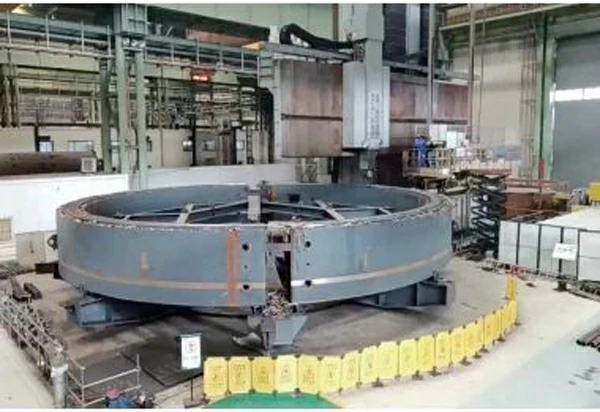
Figure 5 On-site Machining of the Arc Beam

By using the arc beam machining fixture, the positioning and installation of the arc beam can be efficiently and accurately completed. Two arc beams can be installed at once, significantly improving the processing efficiency of the arc beam.

Conclusion

The core component of the underwater salvaging device for the ancient sunken ship, the arc beam, as a super-large welded structural component, requires high manufacturing precision. In the actual production process, using the clamping and positioning fixture and manufacturing process described above ensures not only that each machined arc beam maintains a high level of dimensional consistency but also that all machining accuracies meet the design requirements. The machined arc beam has been successfully used in the underwater salvaging device, completing the salvaging of the sunken ship. This directly confirms the feasibility of the entire arc beam component's machining process and the rationality of the machining fixture structure, significantly improving the production efficiency of the arc beam.

About Openex

Openex is home to a full-service, one-stop-shop, contract manufacturing company producing custom large machined parts and fabrications. Our full large fabrication services including large machining, cutting, welding, rolling, punching, braking, testing, painting, and others.
Know More
envelopephonemap-marker linkedin facebook pinterest youtube rss twitter instagram facebook-blank rss-blank linkedin-blank pinterest youtube twitter instagram