Table of contents
A vacuum chamber is an essential piece of equipment in various scientific and industrial applications. By creating a controlled environment with reduced pressure, vacuum chambers enable precise experiments and manufacturing processes that are not possible under standard atmospheric conditions. This guide will cover the basics of vacuum chambers, their types, applications, key considerations for selecting and using them, and the details of custom fabrication.
A vacuum chamber is a rigid enclosure from which air and other gases are removed by a vacuum pump, creating a low-pressure environment. This controlled environment can simulate outer space conditions, support scientific experiments, and assist in manufacturing processes that require specific atmospheric conditions.
Custom fabrication of vacuum chambers involves designing and manufacturing chambers to meet specific requirements that standard models cannot fulfill. This process is crucial for specialized applications in research, aerospace, medical, and industrial fields.
Openex specializes in the custom fabrication of high-quality vacuum chambers for a wide range of applications. With decades of experience in the industry, we pride ourselves on delivering precision-engineered solutions that meet the unique metal fabrication requirements of our clients.
Our team of experts works closely with clients to understand their specific needs and challenges, ensuring that each custom vacuum chamber is tailored to provide optimal performance and reliability. We utilize advanced CAD software for detailed design and employ state-of-the-art manufacturing techniques to ensure the highest standards of quality and precision.
At Openex, we offer a comprehensive range of metal fabrication services, from initial consultation to fabrication, integration, and testing. Our commitment to excellence and customer satisfaction has made us a trusted partner for organizations in research, aerospace, medical, and industrial sectors.
Vacuum chambers are indispensable tools across various fields, enabling experiments and manufacturing processes that require precise control over atmospheric conditions. By understanding the types, components, applications, key considerations, and the process of custom fabrication, users can effectively select and operate vacuum chambers to achieve their desired outcomes. Whether in scientific research, space simulation, or industrial manufacturing, vacuum chambers play a crucial role in advancing technology and knowledge. Custom fabrication further enhances these capabilities by providing tailored solutions for specialized needs.
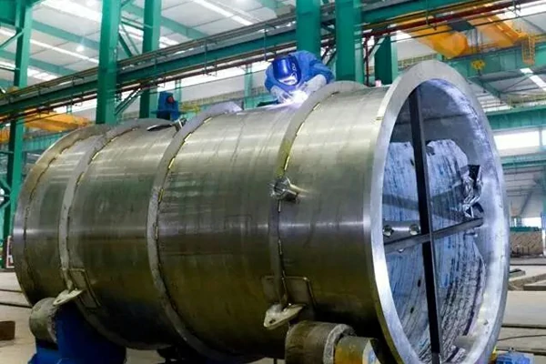
A sunken ancient ship lies beneath the seabed at the mouth of a sea, covered entirely by underwater sediment. To carry out the conservation and archaeological work of the ancient ship, it is necessary to protect the entire ship and its various artifacts completely. Therefore, in the process of salvaging the entire sunken ship, a non-contact method is employed to salvage the ancient ship as a whole to prevent damage. As a key salvaging device throughout the entire process, this apparatus is mainly composed of components such as side end plates, a top beam, a starting frame, and an arc beam, as illustrated in Figure 1.
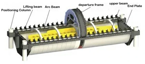
Figure 1 Schematic structure of the underwater sunken ship salvaging device
During the salvaging process, the arc beam components are pre-installed inside the launching frame. The electric motor in the starting frame drives the gear, propelling the arc beam to rotate around the center of the launching frame in a circular motion along the arc rack and the arc roller surface. Several arc beams are connected to form a whole, enveloping the entire sunken ship. The connecting structure between the arc beams is illustrated in Figure 2. Finally, using a lifting beam, all the arc beams, along with the sunken ship, are lifted out of the water.
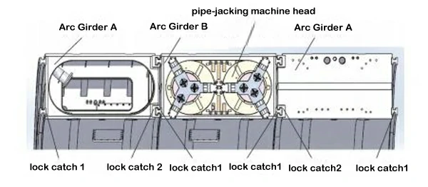
Figure 2 Schematic of the arc beam connection structure
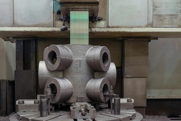
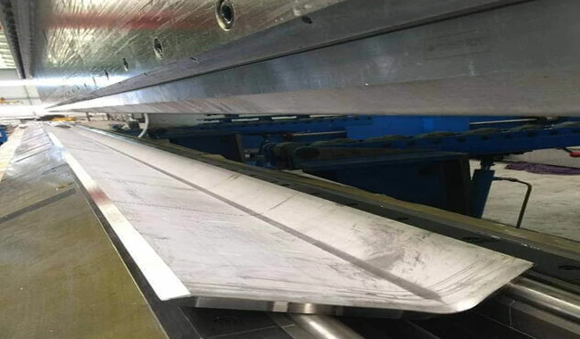
The arc beam components are large welded steel structures made of Q355B material, forming a semi-circular structure with a diameter of approximately 20 meters. The cross-section of the arc beam is a rectangular frame structure with outer dimensions of about 1m × 2m. The device comprises over 20 arc beams of the same size and specifications. The structure of the arc beam components is shown in Figure 3.
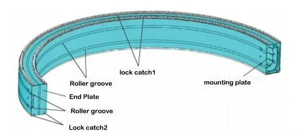
Figure 3
To ensure the smooth operation of the entire arc beam, there are high precision requirements for the manufacturing of the arc beam. After welding, the dimensional tolerances and geometric tolerances of the inner and outer arcs, as well as the upper and lower planes, must be controlled within ±5mm. After mechanical processing, the arc diameter size accuracy of the inner and outer arc roller grooves and the distance size accuracy between the upper and lower plane arc plate male and female locking slot surfaces must be controlled within ±0.4mm. The perpendicularity tolerance between the male and female locking slot mounting surface of the upper and lower plane arc plates and the roller guide groove mounting surface of the inner and outer arc plates must be controlled within ±0.4mm. The coaxiality of the upper and lower arc roller groove mounting surfaces of the inner and outer arcs must be controlled within ±0.4mm.
(1) Welding Fixtures
In order to meet the welding precision requirements of the core arc beam component of the salvaging device, reduce welding deformation, and ensure that the machining allowance on the welding structure of the arc beam is small and uniform for easy subsequent mechanical processing of the mating installation surfaces, the dimensional accuracy of each arc beam, especially the roundness of the arc surface after welding, is controlled within ±5mm. A dedicated welding clamping and positioning fixture for arc beam components has been designed
Overview of Welding Fixture:
A reference point is set on the horizontal ground, a central axis is established perpendicular to the ground, serving as the measurement reference point for the welding fixture of the salvaging device's arc beam. The fixture and parts are oriented with one side near the central axis as the inner side and the opposite side as the outer side. Multiple radial support beams are laid out radially with the central axis as the center, with some instances having 8 radial support beams arranged at equal intervals to form a semi-circle. The radial support beams are arranged in two layers, including bottom radial support beams and top radial support beams. Longitudinal support beams and inclined reinforcing ribs connect the bottom radial support beams, and the top radial support beams provide longitudinal support. Inner and outer positioning blocks are set on the radial support beams. The bottom inner positioning block and bottom outer positioning block are set on the bottom radial support beam, while the top inner positioning block and top outer positioning block are set on the top radial support beam. The outer end face of the bottom inner positioning block and top inner positioning block is at a distance from the central axis equal to the radius of the inner arc surface of the arc beam. The inner end face of the bottom outer positioning block and top outer positioning block is at a distance from the central axis equal to the radius of the outer surface of the outer arc plate of the arc beam. The above errors are controlled within a range of 0.5mm.
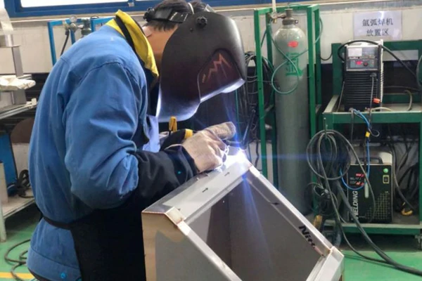
(2) Welding Process
The welding process is described as follows:
To address the manufacturing precision requirements and the issue of batch processing for the core arc beam components of the salvaging device, a set of machining clamping and positioning fixtures for the arc beam components has been specially designed, as shown in Figure 4. The main structural features of the clamping and positioning fixture are described below.
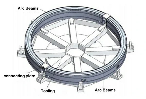
Figure 4 Arc Beam Clamping Form
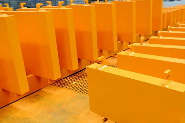
The machining process for the arc beam components is described as follows:
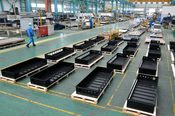
The on-site machining situation in the workshop is shown in Figure 5.
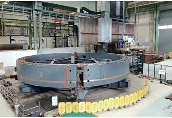
Figure 5 On-site Machining of the Arc Beam
By using the arc beam machining fixture, the positioning and installation of the arc beam can be efficiently and accurately completed. Two arc beams can be installed at once, significantly improving the processing efficiency of the arc beam.
The core component of the underwater salvaging device for the ancient sunken ship, the arc beam, as a super-large welded structural component, requires high manufacturing precision. In the actual production process, using the clamping and positioning fixture and manufacturing process described above ensures not only that each machined arc beam maintains a high level of dimensional consistency but also that all machining accuracies meet the design requirements. The machined arc beam has been successfully used in the underwater salvaging device, completing the salvaging of the sunken ship. This directly confirms the feasibility of the entire arc beam component's machining process and the rationality of the machining fixture structure, significantly improving the production efficiency of the arc beam.
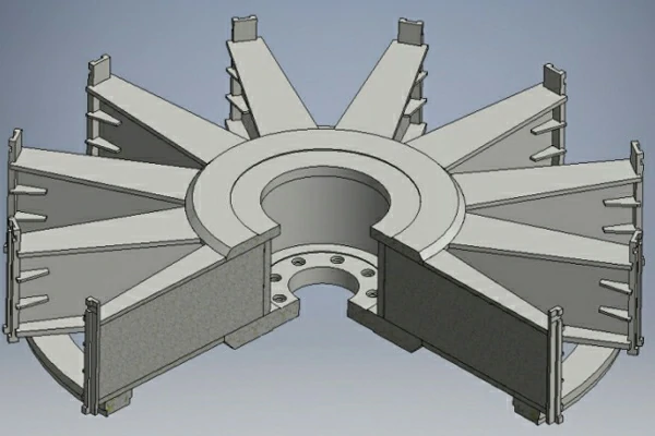
In the ever-evolving landscape of renewable energy, advancements in hydroelectric power generation systems play a pivotal role in shaping a sustainable future. One groundbreaking innovation that takes center stage is the fabrication process of the vertical turbine generator welded structure rotor bracket. This article provides an in-depth exploration of this manufacturing journey, highlighting each crucial step and the transformative impact on the clean energy sector.
Step 1: Design and Engineering Challenges in Traditional Radial Structures
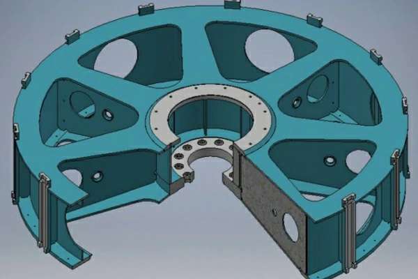
The journey begins with a critical examination of the traditional radial structure of the rotor bracket in a vertical turbine generator unit. This component, although central to the rotor's functionality, presented a host of challenges. Its complex, large, and rigid radial design, subject to intricate forces, required meticulous machining after the rotor shaft's completion. The subsequent thermal fitting of the heated rotor bracket onto the rotor shaft, coupled with the welding of the rib plate, lower ring plate, and hub as an integral unit, posed challenges in maintaining concentricity and incurred significant manufacturing costs.
Step 2: A Paradigm Shift - The Welded Structure Rotor Bracket
The Welded Structure Rotor Bracket introduces a paradigm shift in design philosophy. This innovative approach eliminates the traditional thermal fitting process by adopting an integral welding structure. The core components - rotor shaft, rib plates, upper ring plate, lower ring plate, and vertical ribs - are seamlessly welded together, transforming into a unified and robust integral structure.
Step 3: Benefits of the Integral Welding Structure
The advantages of this integral welding structure are multifaceted. The single-axis design of the rotor shaft, combined with the welding of rib plates on its outer cylindrical surface, provides structural integrity and simplifies the fabrication process. The integration aligns the axis of the rotor shaft precisely with the outer circle of the rotor bracket, eliminating eccentricity issues that plagued traditional radial designs.
Step 4: Enhanced Efficiency and Reliability
By aligning the rotor shaft's axis with the outer circle of the rotor bracket, the integral welding structure minimizes axial runout. This reduction significantly enhances the safety and reliability of the vertical turbine generator unit during operation. The elimination of the thermal fitting structure also streamlines the manufacturing process, saving time and reducing costs.
Step 5: Cost-Effective Manufacturing and Reduced Machining
The integral welding structure not only eliminates the need for the hub thermal fitting but also reduces the machining required in the mating section of the rotor shaft and hub. This substantial reduction in machining time and complexity translates to a more cost-effective manufacturing process, aligning with the broader goal of making renewable energy solutions economically viable.
Step 6: Reliability in Torque Transmission
The torque transmission mechanism sees a fundamental shift with the integral welding structure. The weld seam of the rib plates and the rotor shaft replaces the traditional tight fit associated with hub thermal fitting, ensuring a reliable and secure transmission of torque between the rotor bracket and the rotor shaft.
The fabrication process of the vertical turbine generator welded structure rotor bracket not only addresses the challenges posed by traditional radial structures but also heralds a new era in hydroelectric power generation. This innovative approach, with its integral welding structure, sets the stage for enhanced efficiency, reduced manufacturing costs, and increased reliability in the operation of vertical turbine generators. As the global push for clean and sustainable energy solutions intensifies, such advancements underscore the industry's commitment to transformative technologies that pave the way towards a greener and more sustainable future.
If you are inspired by this innovative approach and wish to explore how similar cutting-edge welding structures or metal fabrication solutions can elevate your projects, we invite you to connect with us. Our team of skilled engineers and craftsmen is ready to collaborate with you on any welding structure or metal fabrication requirements you may have. Contact us today at sales3@openex.com.cn to embark on a journey towards efficiency, reliability, and sustainability in your renewable energy endeavors. Let's shape the future together.
Automobile lightweight is the process of reducing the curb weight of a car as much as possible while ensuring its strength and safety performance. This aims to enhance the car's power, reduce fuel consumption, and decrease exhaust emissions. According to a report from the World Aluminium Association, a 10% reduction in the overall weight of a car can lead to a 6%-8% improvement in fuel efficiency. Research by Volkswagen suggests that for every 100-kilogram reduction in the curb weight, carbon dioxide emissions per kilometer can decrease by 8-11 grams, and fuel consumption per hundred kilometers can be reduced by 0.3-0.5 liters. Therefore, in the current context of increasing pressure to reduce emissions from automobiles, lightweight plays a highly positive role in conserving energy, reducing emissions, and achieving sustainable development goals.
Lightweighting has become a key focus for the development of fuel vehicles, with a target of a 10% reduction in the overall vehicle lightweighting coefficient for gasoline-powered cars by 2025. Given the goals for reducing fuel consumption in gasoline-powered vehicles, the vigorous development of automotive lightweight technologies and the continuous establishment of a technical development and application system for automotive lightweighting become crucial. The 'Energy-saving and New Energy Vehicle Technology Roadmap 2.0' discards the traditional approach of using the overall vehicle equipment mass and the quantity of lightweight materials as measurement standards. Instead, it introduces the overall vehicle lightweighting coefficient as a basis for assessing the level of vehicle lightweighting. It proposes that by 2025, 2030, and 2035, China's gasoline-powered passenger cars should achieve a 10%, 18%, and 25% reduction in the overall vehicle lightweighting coefficient, while freight trucks, tractors, and buses should achieve reductions of 5%, 10%, and 15%, respectively.
In 2022, the penetration rate of new energy vehicles (NEVs) increased rapidly year-on-year, with the national stock of NEVs growing significantly to 13.1 million vehicles. According to statistics from the Ministry of Public Security, the national stock of NEVs reached 13.1 million in 2022, accounting for 4.10% of the total number of vehicles. Deducting the scrapped and deregistered vehicles, this represents an increase of 5.26 million from 2021, a growth of 67.13%. Among these, the stock of pure electric vehicles (EVs) reached 10.45 million, constituting 79.78% of the total NEV stock. In 2022, the national registration of new NEVs was 5.35 million, accounting for 23.05% of the total registered vehicles, an increase of 2.4 million compared to the previous year, marking an 81.48% growth. The number of newly registered NEVs has shown a high-speed growth trend, rising from 1.07 million in 2018 to 5.35 million in 2022.
Compared to traditional fuel vehicles, the demand for weight reduction in new energy vehicles (NEVs) is more urgent:
To meet the technical requirements of lightweight casting in the automotive industry, breakthroughs are currently being made in three aspects: materials, structural design, and processes, according to cutting-edge industry technology:
Among the three major lightweighting methods, material lightweighting serves as the foundation. Based on the use of lightweight materials, the overall vehicle weight is reduced through optimization of structure and upgraded processes. In the development of lightweight materials, the 'Energy-saving and New Energy Vehicle Technology Roadmap 2.0' indicates that China's independent development and application system for lightweight technologies will focus on perfecting the application of high-strength steel in the short term, directing efforts toward establishing a lightweight alloy application system in the medium term, and aspiring to form a multi-material hybrid application system in the long term.
According to the International Iron and Steel Association's USL-AB project, steel types can be classified based on their mechanical properties into low-strength steel (soft steel), high-strength steel, and ultra-high-strength steel. Low-strength steel has a tensile strength (Rm) of <270MPa and a yield strength (Re) of <210MPa. Ultra-high-strength steel has a tensile strength (Rm) of >700MPa and a yield strength (Re) of >550MPa. High-strength steel falls between these two. Low-strength steel includes IF steel and soft steel; ordinary high-strength steel includes carbon-manganese steel, BH steel, high-strength IF steel, and HSLA steel, among others; advanced high-strength steel (AHSS) includes dual-phase steel (DP steel), transformation-induced plasticity steel (TRIP steel), complex phase steel (CP steel), and martensitic steel (MS steel).
Steel accounts for a large portion of the vehicle's weight, approximately 55-60% of the vehicle's total weight. According to the Automotive Materials Network, in the case of a modern car, steel constitutes 55%-60% of the vehicle's weight, cast iron 5%-12%, non-ferrous metals 6%-10%, plastics 8%-12%, rubber 4%, glass 3%, and other materials (paint, various liquids, etc.) 6%-12%. It is evident that steel usage in cars is significant, and the application of high-strength steel plates can reduce the weight of stamped parts, saving energy and reducing the cost of stamped products. High-strength steel plates used for automotive parts can have a tensile strength of 600-800MPa, while the corresponding tensile strength of ordinary cold-rolled soft steel plates is only 300MPa. Currently, the world's largest steel company, Arcelor, has developed the hot-stamped steel plate USIBOR1500. This galvanized plate has a coating mass of 120-160g/m2, and after quenching, it exhibits significant mechanical properties with a strength value of up to 1600MPa.
High-strength steel can be applied to various parts of a vehicle, including:
Multiple projects confirm that high-strength steel can achieve lightweighting without increasing costs. According to the magazine 'Rolling Steel,' to promote the application of high-strength steel in automobiles, the International Iron and Steel Association has organized several projects, including the UltraLight Steel Auto Body (ULSAB), Advanced Concept Vehicle UltraLight Steel Auto Body Program (ULSAB-AVC), and Future Steel Vehicle (FSV).
Aluminum alloy demonstrates significant advantages in weight reduction, performance improvement, and recyclability. Aluminum alloy, the most abundant green metal in the earth's crust, is not only lightweight and high in strength but also easy to shape, has excellent energy absorption, corrosion resistance, and high recyclability value. Additionally, aluminum alloy, while reducing weight, enhances braking performance, provides better handling, improved driving comfort, and outstanding power for vehicles. According to Automotive Materials Network, specific advantages include:
Aluminum alloy requires fewer spot welds for the overall vehicle body, shortening processing steps. Moreover, it is not prone to rust, eliminating the need for anti-rust treatment, significantly improving the efficiency of car assembly. Additionally, due to its low melting point, low corrosion rate, and mild corrosion during usage, aluminum alloy is easy to recycle.
The price of aluminum alloy is only slightly higher than that of high-strength steel and much lower than that of carbon fiber composite materials. The high chemical stability of aluminum alloy makes it less susceptible to corrosion compared to magnesium alloy, limiting its extensive application in the automotive field. Therefore, overall, aluminum alloy is an ideal material for automotive lightweighting at present. In addition, China is the world's largest producer of alumina and electrolytic aluminum, with a high self-sufficiency rate in raw materials.
Aluminum alloy is one of the optimal materials for lightweighting, with considerable potential for medium to long-term growth. Compared to high-strength steel, aluminum alloy has a more pronounced weight reduction effect due to its lower density. Moreover, it does not face issues such as corrosion susceptibility, high processing costs, and the high price of carbon fiber raw materials, which makes recycling more challenging. Furthermore, the excellent metallic properties of aluminum alloy allow for better integration of structural and process lightweighting, achieving comprehensive weight reduction goals. The 'Energy-saving and New Energy Vehicle Technology Roadmap' outlines phased goals for lightweighting in China, with aluminum alloy usage reaching 250kg and 350kg per vehicle by 2025 and 2030, respectively, far surpassing high-strength steel. As the trend toward lightweighting deepens, materials and technologies for lightweighting continue to advance, and aluminum alloy is poised to become the primary material in the automotive market, with clear advantages in long-term growth.
Plastics come in various types and are essential materials for automotive lightweighting. With the emphasis on energy efficiency, emission reduction, and the rise of new energy vehicles, automotive lightweighting has become an industry trend, leading to an increasing use of plastics in automobiles. Based on the different usage characteristics of various plastics, they are generally classified into three types: general plastics, engineering plastics, and specialty plastics. The primary role of engineering plastics in automobiles is to achieve lightweighting, thereby promoting fuel efficiency at high speeds. Developed countries consider the quantity of plastics used in cars as a crucial indicator of automotive design and manufacturing proficiency, with Germany having the highest plastic consumption, accounting for 15% of the overall material usage. According to automotive engineers, replacing some metals with plastics in the high-voltage electrical components of new energy vehicles can reduce weight by around 30% while meeting performance requirements. Currently, using plastic lightweighting in a pure electric vehicle can reduce weight by approximately 100kg, achieving energy savings and emission reduction. The application of engineering plastics in the automotive field has expanded from interior and exterior components to structural and functional parts. According to the Automotive Materials Network, automotive plastics offer many advantages over traditional materials, primarily in terms of being lightweight, providing excellent aesthetic decoration effects, offering various practical application functions, exhibiting good physical and chemical properties, being easy to process and mold, saving energy, and being sustainable.
Japan and the United States are leading in the development of carbon fibers, while China is accelerating its pace, with the domestication rate reaching 47% in 2021. China's carbon fiber industry started in the 1960s, nearly simultaneously with countries like Japan and the United States. However, due to insufficient knowledge reserves and issues related to intellectual property rights, its development has been slow. Additionally, countries like Japan and the United States have monopolized core carbon fiber technologies, resulting in China's overall lag in carbon fiber production technology and equipment. Since 2000, the country has increased its support for independent innovation in the carbon fiber field, designating it as a key research and development project. With strong support from national policies, the domestic carbon fiber industry has made significant breakthroughs in technology, rapidly increased industrialization levels, expanded application areas, and formed carbon fiber clusters, mainly in Jiangsu, Shandong, Jilin, and other regions. Major domestic companies include Jilin Chemical Fiber, CFEC Shenyang, Zhongcai Sci-Tech, Guangwei Composites, among others. According to Forward Industry Research Institute, in 2021, mainland China's carbon fiber production capacity surpassed the United States for the first time, becoming the world's largest capacity country, with a capacity of 63,400 tons, accounting for over 30% of the global total capacity, and a production volume of 24,300 tons, a YoY growth of 30.03%.
The application of carbon fiber in the automotive sector is hindered by material costs, processing technology, and material recycling challenges. According to the Automotive Lightweighting Technology Innovation Strategic Alliance, key obstacles preventing the widespread use of carbon fiber materials in the field of new energy vehicles include:
Magnesium alloy exhibits significant performance advantages and finds applications in various areas such as automotive shells, brackets, armrest structures, and automotive display systems. Being the lightest metal material, magnesium alloy boasts features like low density, high strength, excellent heat dissipation, and superior seismic noise reduction performance. The density of die-cast magnesium alloy is only 2/3 of aluminum alloy and 1/4 of steel, with both specific strength and specific stiffness surpassing those of steel and aluminum alloy and far exceeding engineering plastics. Due to its excellent characteristics, magnesium alloy can be used in automotive shells, brackets, armrest structures, and automotive display systems, with relatively high attention and acceptance from market customers for body components such as lamp heat dissipation brackets, dashboard brackets, steering brackets, central control skeletons, and in-vehicle display screen frames.
The forming methods of magnesium alloy materials include casting processing and plastic forming, with manufacturing processes also restricting the widespread application of magnesium in the automotive field.
According to 'Research and Progress on Automotive Structural Lightweighting,' structural lightweighting refers to the development and design of components through parameter optimization (dimensions, shapes, positions, thickness, etc.), morphological optimization, and topology optimization. The goal is to reduce weight while maintaining or increasing stiffness and strength.
As one of the three main approaches to automotive lightweighting, process lightweighting can effectively help achieve energy savings and weight reduction at the manufacturing level. Lightweighting technology in automobiles aims to integrate lightweight structural design with various lightweight materials and process technologies, considering the characteristics of the adopted lightweight materials, the requirements of lightweight structural design, and the manufacturing technology used to control product costs, all while maintaining or enhancing the performance, safety, and cost-effectiveness of automobiles. Process lightweighting, based on overall lightweight design for automobiles, comprehensively considers the characteristics of adopted lightweight materials, requirements for lightweight structural design, and product cost control in choosing manufacturing technology.
Laser welding technology involves using advanced laser techniques and equipment to automatically assemble and weld a certain number of materials, such as steel and aluminum alloys, with different materials, thicknesses, and coatings, to form a single integrated sheet. These sheets are then stamped to create components that meet the specific requirements for different components based on their functions, material properties, thickness, and corrosion resistance. Laser welding techniques used in automotive body welding mainly include linear welding, angular welding, curved welding, and multi-part assembly welding. This process uses laser equipment to weld materials with different properties into welded sheets, which are then stamped to produce the final required components, making modern cars both lightweight and energy-efficient.
Hydraulic forming uses liquid as a transmission medium. Under the joint action of liquid pressure and the mold cavity, standard pipes or sheets are shaped into structurally complex, single-piece components. This process replaces traditional welding or casting methods, saving processes and maximizing material efficiency. The hydraulic forming technology for high-strength steel can achieve weight reduction and rational space utilization while maintaining safety performance indicators. Hydraulic forming can be divided into sheet hydraulic deep drawing, tube hydraulic bulging, and shell hydraulic forming. According to the difference in the pressure borne by the liquid in the mold cavity, it can be further divided into high-pressure forming and low-pressure forming.
Hot forming technology involves heating sheet metal to the austenite temperature, then hot forming it in the mold. After cooling with water, high-strength martensitic structures are obtained while maintaining the part's good shape. Hot forming addresses drawbacks such as cracking, springback, and wrinkling in the cold forming process. Parts manufactured using this method meet the characteristics of lightweight and high strength, contributing to the lightweighting of automobiles. Over the past decade, hot forming technology has rapidly become the preferred manufacturing technology in the automotive industry.
The three automotive process lightweight technologies have different advantages. In the future, the choice of technology can be based on the characteristics and requirements of different components of the automobile. The biggest advantage of laser welding technology is its ability to weld blanks with different thicknesses, materials, strengths, stamping performance, and surface treatment conditions together before stamping. Hydraulic forming technology excels in shaping complex, high-precision, hollow components in a single step and is suitable for various hollow components with axisymmetric changes in the automotive field, such as exhaust pipes, engines, and subframe main pipes. It has the advantages of increasing the strength and stiffness of formed parts, reducing the number of molds, and lowering production costs. Hot forming technology is suitable for components with high requirements for comfort, strength, and safety. Typical hot-stamped parts include front and rear door side impact bars, front and rear bumper crossbeams, A/B pillars, floor channel, roof reinforcement beams, and suspension fixed brackets. Hot forming achieves the goal of reducing vehicle weight without compromising safety.
Pressure casting is a casting method that fills the mold cavity with liquid or semi-solid metal or alloy, or liquid metal or alloy containing reinforcing phases, under pressure at a relatively high speed to solidify and form the casting. Pressure casting can be divided into low-pressure die casting, high-pressure die casting, vacuum high-pressure die casting, differential pressure die casting, extrusion casting, etc.
Joining technology is one of the key technologies for the development of lightweight manufacturing technology. It is related to many aspects such as the performance, weight, processing technology, assembly, safety, and recycling of the connected structure. Traditional joining technologies mainly include resistance spot welding and inert gas shielded welding/reactive gas shielded welding (MIG/MAG). However, with the increasing need for lightweight design of materials, new joining technologies such as laser welding, riveting and self-piercing riveting, bonding, and composite connections have gradually developed and been applied more widely. Mechanical joining technologies include press welding, clinching, self-piercing riveting, blind riveting, and folding. The advantages of using mechanical joining technology instead of resistance spot welding are that it can be used for various material combinations or laminated materials, allows for coated surfaces, does not require heating (low deformation, does not change material properties), and does not require pretreatment and processing. Bonding technology refers to using suitable adhesives as process materials, adopting appropriate joint forms, and using reasonable bonding processes to achieve the purpose of connection. Adhesive connections produce continuous connections, resulting in a more uniform stress distribution. Compared with spot welding and mechanical connections, which are local and intermittent connections, adhesive connections improve connection stiffness.
3.1. Integration of Die Casting for Cost Reduction and Efficiency Improvement, with Equipment Cost, Mold Manufacturing Difficulty, and Material Requirements as Major Barriers
The integration of die casting combines traditional stamping and welding processes in automobile production into a die-casting process, greatly simplifying the manufacturing process. Traditional automobile manufacturing consists of four major processes: stamping, welding, painting, and final assembly. Stamping involves pressing metal sheets into various components needed for the vehicle body, followed by welding or riveting to produce large aluminum parts. In contrast, integrated die casting uses large-tonnage die-casting machines to combine stamping and welding into a single die-casting step, merging the first two steps into one. This process highly integrates multiple individual and dispersed components, directly casting large parts.
Compared to the traditional 'Stamping + Welding' model, the integrated die casting model demonstrates advantages in several aspects:
The traditional manufacturing process for car bodies mainly consists of four stages: stamping, welding, painting, and final assembly. The main car manufacturers purchase various structural components manufactured by suppliers nationwide through stamping and die-casting, assembling them (including welding, riveting, and gluing) to form the car's body-in-white assembly. In contrast, the integrated die-casting process reduces the workload of stamping and welding and eliminates many gluing process steps, resulting in a significant increase in production efficiency. For example, the Tesla Model Y's rear floor uses integrated die-casting, where all parts are die-cast in one step, applying new alloy materials. The rear floor assembly, cast in one piece, no longer requires heat treatment, reducing manufacturing time from 1-2 hours in traditional processes to 3-5 minutes.
According to Cheqian Information, the cost reduction of batteries is 6.6 times that of the cost increase from switching to aluminum body materials from steel. The next-generation integrated die-cast chassis from Tesla is expected to reduce vehicle weight by 10%, corresponding to a 14% increase in range. For example, using an 80 kWh battery capacity for a typical electric vehicle, adopting an integrated die-casting body for weight reduction while maintaining the range can lead to a reduction of about 10 kWh in battery capacity. Calculated based on a cost of 100 dollars/kWh for lithium iron phosphate battery packs, this can reduce costs by 1,000 dollars.
All these advancements in lightweight technologies, structural optimization, manufacturing processes, and die casting integration collectively aim to enhance efficiency, reduce costs, and contribute to the development of lighter and more sustainable vehicles in the automotive industry.
Heavy machining is a crucial aspect of various industries, from manufacturing and aerospace to construction and automotive. It involves the removal of substantial amounts of material to shape large and complex components. Selecting the right metal for heavy machining is essential to ensure the desired strength, durability, and machinability of the final product. In this comprehensive guide, we will explore the common metals used for heavy machining and the various forms in which they are available. By the end of this article, you will have a solid understanding of the materials that are the backbone of heavy machining.
Let's embark on a journey through the world of heavy machining and the metals that make it possible.
Heavy machining plays a pivotal role in the production of large, complex components used in various industries. It encompasses processes such as milling, turning, drilling, and grinding to remove substantial amounts of material and create intricate shapes. Heavy machining is utilized in applications ranging from manufacturing industrial machinery to shaping aerospace components and constructing critical infrastructure.
The choice of metal for heavy machining depends on the specific application, as different materials offer distinct properties that cater to various needs. Whether it's the strength required for structural components or the corrosion resistance essential in harsh environments, selecting the right metal is paramount.
Forms: Cast iron is often used in heavy machining and can be found in forms like cast iron bars, blocks, and castings.
Types: Common types of cast iron include gray cast iron and ductile iron. Gray cast iron is known for its excellent damping properties, making it suitable for applications like machine beds and engine blocks. Ductile iron offers improved tensile strength and toughness.
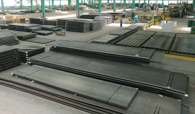
Forms: Steel for heavy machining can be found in various forms, including steel bars, large steel plates, and forged steel components.
Types: Different types of steel are used based on the specific application. Carbon steel and alloy steel are often selected for their strength and machinability.
Forms: Alloy steel for heavy machining can be found in forms like large steel plates, billets, and forgings.
Types: Alloy steels are tailored to provide specific properties, such as increased strength, wear resistance, and heat resistance. Common examples include 4140, 4340, and 8620 alloy steels.
Forms: Stainless steel used in heavy machining can be found in forms like large stainless steel plates, bars, and forgings.
Types: Stainless steel is known for its corrosion resistance and durability. Common grades include 304, 316, and 17-4 PH, among others.
Forms: Nickel-based alloys are used in heavy machining and can be found in forms like large nickel alloy bars, forgings, and plates.
Types: Alloys like Inconel, Hastelloy, and Monel are chosen for their high-temperature resistance and corrosion resistance. They are often used in demanding applications such as aerospace and petrochemical industries.
Forms: Titanium used in heavy machining is typically in the form of large titanium plates, bars, and forgings.
Types: Titanium is known for its high strength-to-weight ratio and corrosion resistance. It is often used in aerospace and military applications.
Forms: Copper and its alloys used for heavy machining can be found in the form of large copper bars, copper plates, and castings.
Types: Copper, bronze, and brass are known for their excellent electrical conductivity, corrosion resistance, and machinability.
Forms: Brass is used for heavy machining and is often found in the form of large brass bars, plates, and castings.
Types: Brass is valued for its corrosion resistance and distinctive appearance.
The form in which a metal is available significantly impacts its utility in heavy machining. Here are some common forms of metals used for heavy machining:
Large plates are one of the primary forms used in heavy machining. They provide a substantial volume of material and are often employed for applications where structural integrity and surface area are essential. Metals like steel, stainless steel, and aluminum are commonly available in the form of large plates. These plates can be cut and machined into various shapes and sizes as needed.
Bars are another common form of metal used in heavy machining. Metal bars come in various dimensions, including round, square, and rectangular shapes. They are often used for creating shafts, axles, and other components that require strength and stability. Steel, alloy steel, and brass are frequently found in the form of bars.
Forgings are metal components that have been shaped through a forging process, which involves applying pressure and heat to mold the material into the desired shape. Forgings are known for their superior strength and durability, making them suitable for heavy machining applications where structural integrity is crucial. Forged components are often used in the aerospace, automotive, and construction industries. Metals like steel, alloy steel, and nickel-based alloys are commonly available in the form of forgings.
Castings are metal parts that are created by pouring molten metal into a mold and allowing it to solidify. They come in various shapes and sizes, making them versatile for heavy machining applications. Castings can be used for producing large, intricate components like engine blocks, turbine housings, and pump casings. Cast iron, nickel-based alloys, and various other metals are available in the form of castings.
The choice of form depends on the specific requirements of the machining project, the size of the component, and the manufacturing processes involved. For instance, large plates, bars, and forgings are suitable for applications where the final product needs to be structurally sound and have specific dimensions. Castings, on the other hand, offer versatility in shape and are ideal for components with complex geometries.
Selecting the right metal for heavy machining is a critical decision that impacts the success of a project. Several factors should be taken into account to make an informed choice:
The material properties of the chosen metal are of paramount importance. Different applications may require specific properties, such as:
Understanding the specific requirements of the application is vital in choosing the right metal. Consider factors such as:
The ease with which a metal can be machined is a significant consideration for heavy machining. Machinability is influenced by factors such as:
Cost is a practical consideration in any machining project. The cost of the metal itself, as well as the associated machining and tooling costs, can significantly impact the overall budget. It's essential to strike a balance between material quality and project affordability.
To achieve successful heavy machining outcomes, it's important to follow best practices throughout the process:
In the world of heavy machining, the choice of metal and its form is a crucial decision that can significantly impact the outcome of a project. Different metals, such as cast iron, steel, alloy steel, stainless steel, nickel-based alloys, titanium, copper, and brass, offer a wide range of properties and characteristics that cater to diverse applications.
Additionally, understanding the form in which these metals are available, such as large plates, bars, forgings, and castings, allows manufacturers to tailor their selection to the requirements of the specific project.
Ultimately, successful heavy machining relies on a combination of material knowledge, careful consideration of application requirements, adherence to best practices, and the skill of experienced operators. By making informed choices and following industry best practices, heavy machining projects can achieve precision, quality, and efficiency while meeting the demands of various industries and applications.
For more information about the metals for heavy machining or metal fabrication, feel free to contact us at yuki.zhou@openex.com.cn
Sheet metal is a versatile material used in various industries for manufacturing a wide range of products. From automotive parts to appliances and electronics, sheet metal assemblies play a crucial role in the production of countless items. However, for beginners looking to understand the art of industrial sheet metal assemblies, it can be quite daunting. In this comprehensive guide, we will demystify the world of industrial sheet metal assemblies, breaking down the fundamental concepts, processes, and best practices to help beginners get started and gain a deeper appreciation for this important field.
Sheet Metal Materials
2.1. Common Sheet Metal Alloys
2.2. Gauge and Thickness
Tools and Equipment
3.1. Hand Tools
3.2. Power Tools
3.3. Sheet Metal Machinery
Cutting and Shearing
4.1. Manual Cutting
4.2. Laser Cutting
4.3. Water Jet Cutting
Bending and Forming
5.1. Press Brakes
5.2. Roll Bending
5.3. Stretch Forming
Joining and Fastening
6.1. Welding
6.2. Riveting
6.3. Adhesives and Fasteners
Design Considerations
7.1. Tolerances and Allowances
7.2. Design for Assembly (DFA)
7.3. Cost Optimization
Finishing and Coating
8.1. Surface Finishes
8.2. Powder Coating
8.3. Anodizing
Quality Control
9.1. Inspection and Testing
9.2. Quality Standards
9.3. Defects and Remedies
Case Studies
10.1. Automotive Industry
10.2. Aerospace Industry
10.3. Electronics Industry
Future Trends
11.1. Industry 4.0 and Automation
11.2. Sustainability
11.3. Advanced Materials
Sheet metal is a flat, thin, and highly versatile material made from metal alloys or steel that is used in a wide range of industrial applications. It can be found in various thicknesses, making it suitable for both structural and decorative purposes. Sheet metal can be easily cut, bent, and formed to create complex shapes and structures, making it an essential component in various industries.
Sheet metal comes in a variety of materials, each with its unique properties. Common types of sheet metal materials include:
Understanding sheet metal materials is crucial for beginners. The choice of material impacts the final product's characteristics, such as strength, weight, and corrosion resistance.
Sheet metal thickness is typically measured in gauge, with lower gauge numbers indicating thicker sheets. Common gauges range from 8 to 30, with 8 gauge being quite thick and 30 gauge extremely thin. Understanding the appropriate gauge for your project is essential to ensure structural integrity and cost-effectiveness.
Sheet metal fabrication requires a range of tools and equipment, from basic hand tools to specialized machinery.
Cutting and shearing are fundamental processes in sheet metal fabrication. The choice of cutting method depends on the project's requirements and the available tools and machinery.
Manual cutting methods include using tin snips, electric shears, and nibblers. These are suitable for small-scale projects and intricate shapes. For straight-line cuts, shears and snips are commonly used, while nibblers excel at cutting curves and irregular shapes.
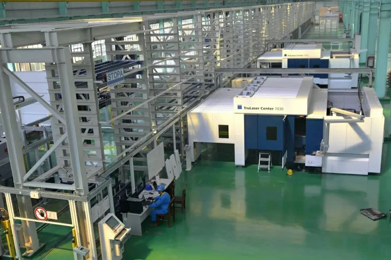
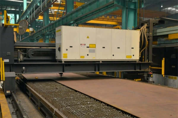
Laser cutting is a highly precise and efficient method of cutting sheet metal. It utilizes a high-energy laser beam focused on the material to make clean and accurate cuts. Laser cutting is favored for its ability to cut complex shapes with minimal heat-affected zones, reducing the risk of warping or deformation. It's commonly used in industries like aerospace, automotive, and electronics where precision is critical.
Please visit laser cutting service page for more information about our laser-cutting capabilities.
Water jet cutting is another method for precisely cutting sheet metal. It uses a high-pressure stream of water mixed with abrasive particles to cut through the material. Water jet cutting is versatile and can cut through a wide range of materials, including metals, plastics, and composites. It's particularly useful for materials that may be sensitive to heat, as there is minimal heat transfer during the cutting process.
Our water jet cutting capability please click water jet cutting.
Bending and forming sheet metal is essential for creating three-dimensional structures. The primary methods for shaping sheet metal include press brakes, roll bending, and stretch forming.
Press brakes are machines designed to bend and shape sheet metal into precise angles and curves. They consist of a top tool (punch) and a bottom tool (die), between which the sheet metal is placed. By adjusting the position of the punch and die and applying controlled force, press brakes can create a wide variety of bends and shapes. This process is commonly used in the manufacture of components for cabinets, enclosures, and structural parts.
More about our press braking capability.
Roll bending machines, also known as plate rolls, are used to create cylindrical or conical shapes by passing the sheet metal between three rollers. The upper roller and two lower rollers are adjusted to form the desired curve. Roll bending is often used in industries like HVAC (Heating, Ventilation, and Air Conditioning) to make cylindrical ducts and tanks.
More about our roll bending capability.
Stretch forming is a specialized technique used for creating complex, contoured shapes in sheet metal. The sheet is clamped around its edges and stretched over a form using hydraulic or mechanical force. This method is used in industries such as aerospace and automotive for producing parts with aerodynamic or intricate shapes.
Assembling sheet metal components often involves joining and fastening methods to create a structurally sound and reliable final product. Common techniques include welding, riveting, and the use of adhesives and fasteners.
Welding is a widely used method for permanently joining sheet metal components. Various welding processes can be employed, such as MIG (Metal Inert Gas) welding, TIG (Tungsten Inert Gas) welding, and spot welding. The choice of welding method depends on the specific application and the type of sheet metal being used. Welding is commonly used in the automotive, construction, and manufacturing industries.
More about our welding capability.
Riveting involves joining two or more pieces of sheet metal by driving a rivet through holes in the metal and then deforming the end of the rivet to secure the components together. Rivets provide a strong and reliable connection and are frequently used in aerospace and construction.
Adhesives and fasteners can also be used to join sheet metal components. Adhesive bonding is suitable for lightweight, non-structural applications and can provide a clean and aesthetically pleasing finish. Fasteners like screws and bolts are used in situations where components need to be disassembled for maintenance or repair.
Effective sheet metal assembly design is critical to achieving a successful and cost-efficient end product. Design considerations encompass tolerances and allowances, design for assembly (DFA) principles, and cost optimization.
Understanding tolerances and allowances is crucial for ensuring that components fit together correctly. Tolerances specify the allowable variation in dimensions, while allowances account for variations in the manufacturing process. It's important to strike a balance between tight tolerances for precise fitment and allowances that allow for practical manufacturing.
Design for Assembly is a set of principles aimed at simplifying the assembly process and reducing production costs. It involves designing components that are easy to handle, align, and connect. Some DFA principles include minimizing the number of components, using self-locating and self-fastening features, and designing for ease of access during assembly.
Cost optimization in sheet metal assemblies involves finding the right balance between material costs, manufacturing processes, and labor expenses. This includes selecting the most cost-effective materials, minimizing waste, and streamlining production methods. Design choices that can affect cost optimization include nesting parts efficiently to reduce material waste and selecting manufacturing methods that minimize labor and machine time.
The appearance and performance of sheet metal assemblies can be significantly enhanced through finishing processes and coatings.
Surface finishes are applied to sheet metal components to improve their appearance, durability, and corrosion resistance. Common surface finishes include brushing, polishing, and grinding, which can provide a smooth and reflective surface. In addition to aesthetics, surface finishes can also improve paint adhesion and reduce the risk of corrosion.
Powder coating is a popular method for applying a durable and attractive finish to sheet metal components. In this process, a dry powder is electrostatically applied to the metal surface, and then the coated component is heated to allow the powder to melt and form a smooth and protective layer. Powder coating is environmentally friendly, offers a wide range of color options, and is resistant to chipping and scratching.
Anodizing is a surface treatment primarily used for aluminum sheet metal. It involves immersing the metal in an electrolyte bath and applying an electric current to create a controlled oxidation layer on the surface. Anodizing provides corrosion resistance, enhances surface hardness, and offers decorative color options.
Quality control is a critical aspect of sheet metal assembly to ensure that the final product meets industry standards and customer expectations. To know how we control the quality of our metal parts visit Quality Assurance.
Regular inspection and testing of sheet metal components during and after the assembly process help identify defects and deviations. Non-destructive testing methods, such as ultrasonic testing and visual inspection, are commonly used to assess the integrity of welds and joints. Quality control practices also include measuring critical dimensions and checking for surface imperfections.
Adhering to industry-specific quality standards and certifications is essential for ensuring the reliability and safety of sheet metal assemblies. Depending on the industry, these standards may include ISO 9001 for general quality management, AS9100 for aerospace, or ISO/TS 16949 for the automotive industry.
Sheet metal assemblies may be susceptible to various defects, such as porosity in welds, cracks, and surface imperfections. Identifying defects early in the manufacturing process is crucial. Remedies may include rework, repairing the defect, or in some cases, scrapping and starting over to maintain quality and safety standards.
To further illustrate the importance and versatility of sheet metal assemblies, let's explore a few case studies from different industries.
Sheet metal assemblies are integral to the automotive industry. They are used to manufacture vehicle body panels, chassis components, and a variety of interior and exterior parts. Automotive manufacturers use advanced assembly techniques to meet stringent safety and performance requirements while keeping production costs in check. The utilization of high-strength steels, precision welding, and advanced paint and coating technologies help produce vehicles that are both safe and aesthetically appealing. Sheet metal assemblies also play a role in lightweighting initiatives, contributing to improved fuel efficiency and reduced emissions.
The aerospace industry relies on sheet metal assemblies for building aircraft structures, from fuselages to wings and engine components. Precision and reliability are paramount in aerospace applications, as safety is the top priority. Advanced materials like titanium and aluminum alloys are used, and components are often subjected to stringent quality control processes, including non-destructive testing for critical welds and joints. The aerospace industry also focuses on reducing weight and improving aerodynamics through innovative sheet metal design and assembly methods.
In the electronics industry, sheet metal assemblies are used to create enclosures and chassis for electronic devices, such as computer servers, telecommunications equipment, and consumer electronics. Sheet metal is valued for its ability to shield against electromagnetic interference (EMI) and protect delicate electronic components from external influences. Precision manufacturing, including laser cutting and CNC (Computer Numerical Control) machining, is crucial to ensure that electronic devices are not only functional but also compact and visually appealing.
For more cases, please visit our Industries Served page.
The world of industrial sheet metal assemblies is constantly evolving. To stay ahead of the curve, it's essential to be aware of emerging trends and technologies that are shaping the industry's future.
The advent of Industry 4.0, characterized by the integration of digital technologies and the Internet of Things (IoT), is transforming sheet metal assembly processes. Automation, robotics, and smart manufacturing systems are becoming more prevalent, improving efficiency and reducing the risk of errors. These technologies enable real-time monitoring and data analysis, helping manufacturers optimize production and minimize waste.
Sustainability is a growing concern in the sheet metal industry. Manufacturers are increasingly adopting eco-friendly practices, such as recycling scrap metal and reducing energy consumption. Lightweight materials and designs that improve fuel efficiency in transportation industries contribute to sustainability efforts. Additionally, environmentally friendly surface treatments and coatings are being developed to reduce the environmental impact of sheet metal assembly processes.
The development of advanced materials, including high-strength alloys and composites, is driving innovation in sheet metal assembly. These materials offer improved strength-to-weight ratios and corrosion resistance, making them valuable in industries where performance and durability are critical. As advanced materials become more accessible, they will continue to shape the design and manufacturing of sheet metal components.
Industrial sheet metal assemblies are a fundamental part of modern manufacturing across a wide range of industries. For beginners looking to understand this complex and versatile field, it's essential to grasp the basics of sheet metal materials, tools, and fabrication processes. Cutting, bending, joining, and finishing methods all play vital roles in shaping sheet metal into functional and aesthetically pleasing components.
Effective design, quality control, and adherence to industry standards are key to producing safe and reliable sheet metal assemblies. Case studies across the automotive, aerospace, and electronics industries highlight the significance of sheet metal in diverse applications. Furthermore, the future of sheet metal assemblies is marked by technological advancements, including Industry 4.0 integration, sustainability practices, and the development of advanced materials.
As you continue to explore the world of industrial sheet metal assemblies, remember that the key to success lies in a strong foundation of knowledge, an understanding of best practices, and a commitment to quality and innovation. Whether you're a beginner or an experienced professional, the world of sheet metal assembly offers endless opportunities for creativity and advancement in manufacturing.
Metal fabrication is an essential process in various industries, and the quality and durability of the finished parts often depend on the surfacing treatments applied. These treatments not only enhance the aesthetic appeal of the metal parts but also improve their resistance to corrosion, wear, and other forms of damage. In this blog, we will delve into the fascinating world of surfacing treatments for metal fabrication parts, exploring a range of techniques and their applications.
Electroplating is a popular surfacing treatment that involves depositing a layer of metal onto a substrate using an electrolytic process. Common metals used for electroplating include chromium, nickel, and zinc. This treatment offers several benefits, such as corrosion resistance, improved appearance, and enhanced electrical conductivity.
Applications:
Powder coating is a dry finishing process that involves applying a free-flowing, dry powder to a metal surface. The coated part is then cured using heat, allowing the powder to melt and form a hard, durable finish. This technique offers an array of colors and textures and is known for its environmental friendliness, as it generates minimal waste.
Applications:
Anodizing is an electrochemical process that converts the surface of aluminum into a durable, corrosion-resistant, and decorative finish. It involves immersing the aluminum part in an electrolyte solution and applying an electrical current. The resulting oxide layer can be dyed to achieve various colors.
Applications:
Thermal spray coating is a versatile surfacing treatment that involves spraying a wide range of materials, such as metals, ceramics, and polymers, onto a metal surface. The sprayed particles adhere to the substrate, creating a protective and wear-resistant layer.
Applications:
Passivation is a chemical process used to remove free iron from the surface of stainless steel, creating a passive film that enhances the metal's corrosion resistance. This treatment is crucial for maintaining the longevity and appearance of stainless steel parts.
Applications:
Galvanization is the process of applying a layer of zinc to the surface of steel or iron to protect it from corrosion. There are two primary methods: hot-dip galvanizing and electro-galvanizing, each suited to specific applications.
Applications:
Metal polishing is a finishing process that enhances the appearance of metal surfaces by removing imperfections and creating a smooth, shiny finish. Various techniques, including abrasive polishing and chemical polishing, can be used to achieve different levels of gloss and smoothness.
Applications:
Surfacing treatments for metal fabrication parts play a vital role in enhancing their durability, appearance, and functionality. The choice of treatment depends on the specific requirements of the part and the intended application. By understanding the various surfacing options available, manufacturers can ensure that their metal fabrication parts meet the highest standards of quality and performance. Whether you're looking for corrosion resistance, improved aesthetics, or enhanced wear resistance, there is a surfacing treatment that can meet your needs.
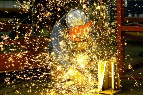
In the world of metal fabrication, there's a place where creativity and craftsmanship converge, where raw materials are transformed into functional art, and that place is the welding shop. Welders are the unsung heroes of this industry, toiling away in the heat and sparks, forging masterpieces from cold, lifeless steel.
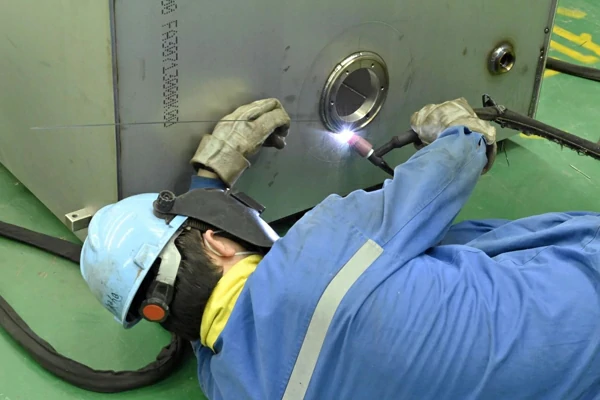
Welding is not just a job; it's an art form. It requires a combination of technical expertise and a keen artistic eye. Welders are akin to sculptors, shaping metal into beautiful and functional structures. They carefully choose the right welding technique, adjust the heat, and create intricate, precise welds to ensure the final product is both aesthetically pleasing and structurally sound.
Welders are like alchemists, wielding their tools to manipulate various metals into a plethora of shapes and sizes. Whether it's mild steel, stainless steel, aluminum, or exotic alloys, welders understand the unique properties of each material. They know how to work with different metals to achieve the desired strength, durability, and appearance. This knowledge and expertise are the foundation of their craft.
The welding shop is a symphony of tools and equipment, each with its role in the creation process. From the loud crackle of the welding machine to the rhythmic clang of hammers and the hiss of the plasma cutter, the welding shop is a place where each tool contributes to the final masterpiece. Precision is key, and welders are skilled in the operation of various tools to ensure the end product meets exacting standards.
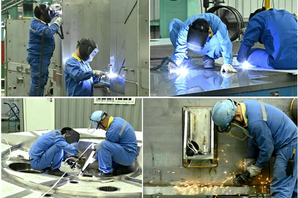
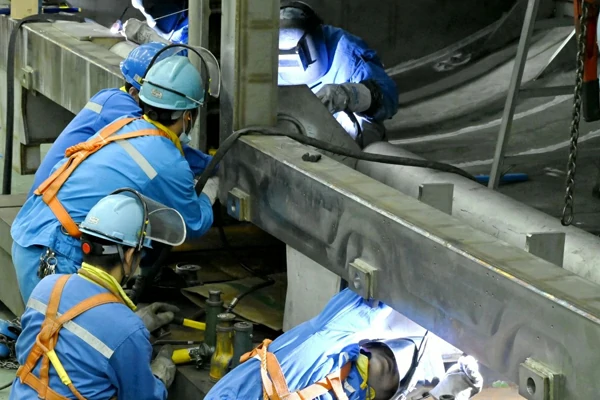
Working in a welding shop is not just about skill but also about safety. Welders are diligent in following safety protocols to protect themselves and their colleagues from the inherent risks of the job. They wear protective gear like welding helmets, gloves, and flame-resistant clothing. Proper ventilation systems are in place to manage fumes and gases, and fire safety equipment is readily available. Welders are aware that their craft requires precision, but it also demands the highest level of safety.
Welders are problem solvers. They take on projects that seem impossible and find innovative solutions. Whether it's crafting intricate metal artwork, repairing heavy machinery, or fabricating custom architectural pieces, welders have the skills and determination to turn dreams into reality. Their creativity knows no bounds, and they constantly push the limits of what can be achieved with metal.
Welders in the welding shop are the backbone of metal fabrication. They are the artisans who fuse raw materials into beautiful, functional pieces. They wield their tools with skill and precision, transforming metal into works of art. With a deep understanding of materials, a symphony of tools at their disposal, and an unwavering commitment to safety, welders are the heroes behind the scenes, making the impossible possible. So, the next time you see a stunning metal structure or a finely crafted piece of artwork, remember the welders working hard in the welding shop, and the artistry and dedication they bring to their craft.
If you've been inspired by the dedication and craftsmanship of welders in the welding shop, consider how their skills can bring your metal fabrication projects to life. Whether you have a unique idea for a custom metal piece, need repairs for heavy machinery, or require expert welding services, don't hesitate to reach out to a skilled metal fabricator. Your vision can become a reality with the help of these talented artisans. Contact us today and let's discuss how we can turn your metal dreams into tangible masterpieces!
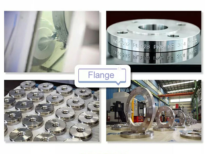
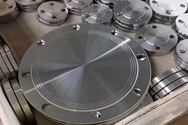
Steel flanges are not the most glamorous components in the world of industrial engineering, but their significance cannot be overstated. These seemingly simple, circular devices serve as critical elements in pipelines, allowing for the assembly, disassembly, and maintenance of a wide range of systems. Steel flanges are used in diverse industries, from oil and gas to petrochemical, manufacturing, and beyond. In this blog, we'll delve into the power and versatility of steel flanges, exploring their types, applications, and the crucial role they play in keeping our infrastructure and industrial processes running smoothly.
A flange is a flat, circular piece of steel with evenly spaced holes for bolts. It's designed to connect or disconnect two sections of pipes or other equipment with ease. Flanges are essential for various industrial applications, primarily because they facilitate easy maintenance, repairs, and assembly of pipelines or equipment.
Steel is the most common material used for flanges due to its exceptional strength, durability, and resistance to corrosion. Steel flanges come in various sizes, shapes, and types to suit different applications and pressure requirements. The choice of steel grade and flange type depends on the specific conditions and demands of the system in which they are employed.
Steel flanges are categorized into different types, each serving a specific purpose in various applications. Here are some of the most common types:
Steel flanges find their applications across a wide range of industries due to their versatility and durability. Let's take a closer look at some of these applications:
The power and versatility of steel flanges rely not only on their material and design but also on the quality of manufacturing and proper maintenance. Low-quality flanges can lead to system failures, leaks, and costly repairs. Regular inspection, maintenance, and, if necessary, replacement of flanges are crucial to prevent issues in industrial processes.
When selecting steel flanges for an application, it's vital to consider factors such as pressure ratings, temperature resistance, material compatibility, and corrosion resistance. Choosing the right type of flange and ensuring it meets the specifications of the system is essential.
In addition to the quality of the flanges themselves, the bolts and gaskets used for assembly are equally important. Proper torqueing of the bolts is critical to prevent leaks and maintain the integrity of the connection.
Steel flanges may not be the most glamorous components in the world of industrial engineering, but their significance is undeniable. They are the unsung heroes that enable the smooth operation of critical systems in various industries, from oil and gas to manufacturing and construction. The power and versatility of steel flanges lie in their durability, resistance to corrosion, and the ease with which they allow for the assembly, disassembly, and maintenance of pipelines and equipment.
As technology and materials science continue to advance, steel flanges will only become more efficient and reliable, playing an increasingly pivotal role in the global infrastructure. It's a testament to the often-overlooked components that keep our modern world running smoothly. So, the next time you see a steel flange, remember the power it holds behind the scenes, quietly supporting the systems that drive our society.
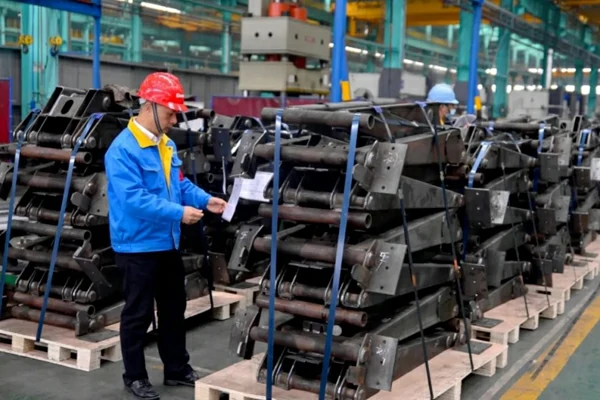
When we think of manufacturing, we often picture high-tech machines, assembly lines, and complex engineering processes. However, at the heart of many manufacturing industries lies a fundamental component – metal parts. Metal parts are the unsung heroes of countless products we encounter in our daily lives, from automobiles and electronics to household appliances and even aerospace technology.
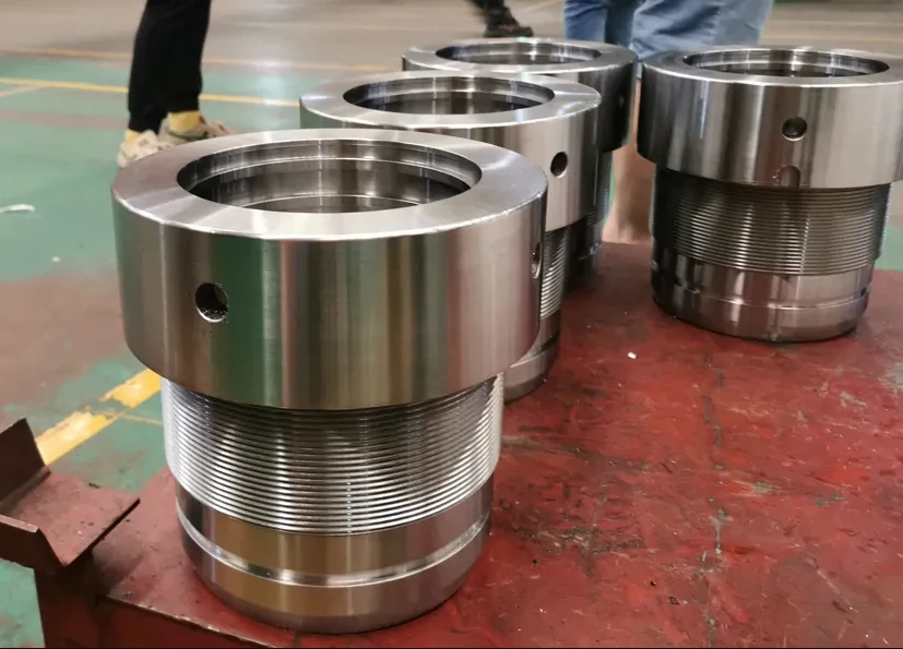
Metal parts serve as the building blocks for most mechanical devices and structures. They are used to create the framework, joints, and connectors that make everything from your smartphone to a skyscraper function as intended. The importance of metal parts in manufacturing cannot be overstated, as they form the backbone of various industries. Let's explore why they are so crucial:
Metals are known for their remarkable strength and durability. This makes them ideal for parts that must withstand high stresses, heavy loads, and harsh environmental conditions. From the chassis of a car to the framework of a bridge, metal parts provide the structural integrity required for safety and long-term performance.
Manufacturing processes for metal parts are highly sophisticated and precise. Computer Numerical Control (CNC) machining, 3D printing, and other advanced techniques allow for the creation of intricate and complex components with exacting tolerances. This precision is essential for applications where even the slightest deviation can lead to malfunction or failure.
Many metals exhibit excellent heat resistance properties. This is crucial for applications involving high temperatures, such as jet engines, industrial ovens, and rocket propulsion systems. Metal parts can withstand extreme conditions without deforming or losing their structural integrity.
Metals are excellent conductors of electricity and heat. This property is utilized in various applications, from electrical wiring to heat sinks in electronic devices. The ability to efficiently transmit heat and electrical signals is pivotal for optimal device performance.
While some metals are prone to corrosion, others, like stainless steel and aluminum, are known for their corrosion resistance. This makes them suitable for outdoor applications and in environments where exposure to moisture and chemicals is common.
The world of metal parts is vast and encompasses a wide range of applications. Here are some key areas where metal parts play a crucial role:
As technology and materials science continue to advance, the world of metal parts is also evolving. The development of new alloys, surface treatments, and manufacturing techniques is expanding the possibilities for metal parts in various industries. Additionally, the push for sustainability has led to the exploration of lightweight materials, including aluminum and titanium, to reduce energy consumption and improve fuel efficiency in transportation.
In conclusion, metal parts are the unsung heroes of the manufacturing world. Their importance in creating safe, reliable, and efficient products cannot be overstated. As we continue to push the boundaries of technology and engineering, metal parts will remain at the forefront of innovation, enabling us to create ever more advanced and sophisticated products. The next time you pick up your smartphone or drive your car, remember the integral role that metal parts play in making it all possible.
As a professional metal parts fabrication company, we understand the pivotal role that metal components play in various industries, and we take great pride in being a part of this dynamic and ever-evolving sector. Our commitment to precision engineering, quality, and innovation drives us to meet the diverse needs of our clients. In the following sections, we will discuss our approach to metal parts fabrication, our capabilities, and the value we bring to our clients.
At Openex, we are dedicated to delivering metal parts that exceed our clients' expectations. Our approach to metal parts fabrication revolves around the following core principles:
Precision is paramount in the world of metal fabrication. We employ cutting-edge technology and highly skilled professionals to ensure that each component we produce adheres to strict tolerances and quality standards. This unwavering commitment to precision is what sets us apart in the industry.
With a wide range of metals at our disposal, we have the expertise to recommend the most suitable materials for each project. Whether it's stainless steel, aluminum, titanium, or specialty alloys, we understand the unique properties of each material and how to leverage them for optimal results.
No two projects are exactly alike, and we recognize the importance of tailored solutions. We work closely with our clients to understand their specific needs and design custom metal parts that align with their goals, whether it's for automotive, aerospace, electronics, construction, or any other industry.
We are committed to environmental responsibility and sustainability. As the world looks toward more eco-friendly manufacturing practices, we actively explore ways to reduce waste, conserve energy, and employ materials and techniques that have a smaller environmental footprint.
Openex boasts a wide array of capabilities to meet the diverse demands of our clients. Some of our core competencies include:
Collaborating with us for your metal parts fabrication needs means benefiting from our expertise, commitment to excellence, and dedication to delivering superior products. When you choose us, you can expect:
In the ever-evolving world of metal parts fabrication, Openex is your trusted partner for delivering excellence, innovation, and quality. Contact us today to discuss your project, and let us demonstrate how we can add value to your business through our expertise in metal parts fabrication.