The function of stainless steel housing depends on the specific application and the type of housing used. Here we list some of the common functions:
Protection: One of the primary functions of housing is to provide protection to the components or equipment housed inside. This can include protection from environmental factors such as weather, moisture, and dust, as well as protection from physical damage, theft, or tampering.
Enclosure: Housing can also function as an enclosure, enclosing the components or equipment inside and preventing them from being exposed to the surrounding environment. This is particularly important in applications where the components or equipment require a controlled environment to function properly.
Organization: Housing can also help to organize and structure the components or equipment inside, ensuring that they are arranged in an efficient and logical manner. This can help to improve productivity and reduce downtime in industrial or manufacturing applications.
Aesthetic Appeal: Housing can also have an aesthetic function, providing a visually appealing appearance to the components or equipment inside. This is particularly important in applications where the housing is visible to customers or visitors, such as retail or commercial settings.
Structural Support: In some applications, housing can also provide structural support to the components or equipment inside. This is particularly important in applications where the equipment is large, heavy, or requires a stable foundation to function properly.
The functions of housing are diverse and depend on the specific application and the requirements of the components or equipment housed inside.
With years of experience and expertise in the industry, Openex established ourselves as a reliable and trusted name in the market, providing our clients with superior-quality stainless steel housing that meets their specific needs and requirements. Contact us today to learn more about our services and how we can help you with your stainless steel housing needs.
Stainless steel housing refers to a housing made entirely or partially of stainless steel. Stainless steel is a corrosion-resistant alloy that contains at least 10.5% chromium. It also contains varying amounts of other elements such as nickel, molybdenum, and titanium, which enhance its strength, durability, and corrosion resistance.
Stainless steel housing is commonly used in applications where corrosion resistance, strength, and durability are essential. Some of the applications of stainless steel housing include:
Electronic Enclosures: Stainless steel housing is commonly used in the construction of electronic enclosures such as control panels, junction boxes, and cabinets. The corrosion-resistant properties of stainless steel make it ideal for protecting sensitive electronics from environmental factors such as moisture and chemicals.
Food Processing Equipment: Stainless steel housing is commonly used in the construction of food processing equipment such as mixers, blenders, and conveyors. Stainless steel is easy to clean, hygienic, and resistant to corrosion from food acids and cleaning chemicals.
Medical Equipment: Stainless steel housing is also used in the construction of medical equipment such as surgical instruments, hospital beds, and carts. Stainless steel is easy to sterilize, corrosion-resistant, and durable, making it ideal for use in medical environments.
Aerospace and Defense: Stainless steel housing is commonly used in aerospace and defense applications such as aircraft parts, missile components, and armored vehicles. Stainless steel's strength and corrosion resistance make it ideal for use in high-stress environments.
Architectural Applications: Stainless steel housing is also used in architectural applications such as building facades, handrails, and staircases. Stainless steel's aesthetic appeal, durability, and low maintenance requirements make it a popular choice for modern architectural designs.
Overall, stainless steel housing is a versatile and durable material that can be used in a wide range of applications where corrosion resistance, strength, and durability are essential.
With years of experience and expertise in the industry, we have established ourselves as a reliable and trusted name in the market, providing our clients with superior-quality stainless steel housing that meets their specific needs and requirements. Contact us today to learn more about our services and how we can help you with your stainless steel housing needs.
Stainless steel has countless applications in any industry. It is the most popular choice of materials used in metal fabrication for home appliances and other objects that must stay clean. Stainless steel can be formed into various shapes and sizes by processes such as casting, forging, rolling, and extrusion. It is also easy to clean and maintain, making it a popular material choice in many industries.
What is stainless steel?
Stainless steel is a type of steel alloy that is known for its high resistance to corrosion and staining, as well as its strength and durability. It is composed primarily of iron, with a minimum of 10.5% chromium content by mass, and may also contain other alloying elements such as nickel, molybdenum, and manganese.
The high chromium content in stainless steel creates a passive layer of chromium oxide on the surface of the metal, which prevents corrosion and oxidation. This makes stainless steel highly resistant to rust and staining, even in harsh environments.
Stainless steel is a versatile material that is used in a wide range of applications, including kitchen appliances, cutlery, medical equipment, construction materials, and in the production of chemical and pharmaceutical processing equipment. It is also commonly used in the automotive and aerospace industries.
Application of stainless steel
Stainless steel has a wide range of applications in various industries, including:
Kitchen appliances: Stainless steel is a popular material choice for kitchen appliances such as refrigerators, ovens, and dishwashers, due to its corrosion resistance and aesthetic appeal.
Cutlery: Stainless steel is commonly used to make cutlery, as it is durable, easy to clean, and does not corrode or stain.
Medical equipment: Stainless steel is a popular material choice for medical equipment, such as surgical instruments, implants, and dental equipment, due to its hygienic properties and resistance to corrosion.
Construction materials: Stainless steel is used in a variety of construction applications, including cladding, roofing, and structural support, due to its strength and durability.
Chemical and pharmaceutical processing equipment: Stainless steel is often used in the production of chemical and pharmaceutical processing equipment, as it is highly resistant to corrosion and contamination.
Automotive and aerospace industries: Stainless steel is used in various parts of automobiles and airplanes, due to its strength, durability, and resistance to corrosion.
Consumer products: Stainless steel is used in a wide range of consumer products, such as watches, jewelry, and electronics, due to its aesthetic appeal and durability.
Oil and gas industry: Stainless steel is used in the oil and gas industry for applications such as pipelines, offshore platforms, and processing equipment, due to its resistance to corrosion in harsh environments.
Water treatment: Stainless steel is often used in water treatment plants for pipes, valves, and other equipment, due to its resistance to corrosion and ease of maintenance.
Pulp and paper industry: Stainless steel is used in the pulp and paper industry for applications such as tanks, pipes, and bleaching equipment, due to its resistance to corrosion and strength.
Renewable energy: Stainless steel is used in renewable energy applications such as wind turbines, solar panels, and hydropower plants, due to its strength and resistance to corrosion.
Rail transportation: Stainless steel is used in the rail industry for applications such as train carriages, track components, and station architecture, due to its strength and resistance to corrosion.
Architecture: Stainless steel is often used in architectural applications such as building facades, bridges, and sculptures, due to its aesthetic appeal and durability.
Marine industry: Stainless steel is used in the marine industry for applications such as boat components, dock hardware, and seawater intake systems, due to its resistance to corrosion in saltwater environments.
Its versatility and durability make it a popular material choice in many different industries.
Benefits of Stainless Steel
Stainless steel has a number of benefits that make it a popular material choice for many applications, from consumer products to heavy industry applications. Some of the main benefits of stainless steel include:
Corrosion resistance: Stainless steel is highly resistant to rust and corrosion, making it an ideal material choice for applications in harsh and corrosive environments.
Strength and durability: Stainless steel is a strong and durable material that can withstand high temperatures and extreme conditions, making it ideal for use in applications that require high strength and durability.
Aesthetic appeal: Stainless steel has a modern and sleek appearance that is often used in architecture, interior design, and consumer products.
Hygienic: Stainless steel is easy to clean and has a non-porous surface that is resistant to bacteria and germs, making it a popular material choice for medical equipment, food processing, and pharmaceuticals.
Recyclable: Stainless steel is 100% recyclable and can be reused to create new products, making it an environmentally friendly material choice.
Versatility: Stainless steel can be formed into various shapes and sizes, making it a versatile material that can be used in a wide range of applications.
Low maintenance: Stainless steel requires minimal maintenance, making it a cost-effective material choice in the long run.
Types of stailess steel
There are many different types of stainless steel, which are classified based on their microstructure, composition, and properties. Here are some of the most common types:
Austenitic Stainless Steel: This is the most widely used type of stainless steel, which is non-magnetic and highly corrosion-resistant. It contains high levels of nickel and chromium, with some grades also containing molybdenum, titanium, and/or nitrogen. Examples include 304, 316, and 321.
Ferritic Stainless Steel: This type of stainless steel is magnetic and has a lower corrosion resistance than austenitic stainless steel. It contains high levels of chromium, with some grades also containing small amounts of nickel or molybdenum. Examples include 409 and 430.
Martensitic Stainless Steel: This type of stainless steel is magnetic and has a high strength and hardness. It contains high levels of chromium and carbon, with some grades also containing small amounts of nickel or molybdenum. Examples include 410 and 420.
Duplex Stainless Steel: This type of stainless steel has a mixed microstructure of austenite and ferrite, with high levels of chromium, nickel, and molybdenum. It has a high strength and corrosion resistance, particularly in harsh environments. Examples include 2205 and 2507.
Precipitation Hardening Stainless Steel: This type of stainless steel can be strengthened through a heat treatment process that causes precipitation of hardening phases. It has a high strength and corrosion resistance, particularly in aerospace and chemical processing applications. Examples include 17-4 PH and 15-5 PH.
Austenitic-Ferritic (Duplex) Stainless Steel: This type of stainless steel is a combination of austenitic and ferritic stainless steels, providing a balance of strength and corrosion resistance. It contains high levels of chromium, nickel, and molybdenum, and is commonly used in applications such as chemical processing, oil and gas, and marine environments.
Super Austenitic Stainless Steel: This type of stainless steel contains high levels of chromium, nickel, and molybdenum, as well as nitrogen and copper. It has excellent corrosion resistance in acidic and chloride environments, and is used in applications such as chemical processing, pulp and paper, and desalination.
High-Performance Stainless Steel: These are specialized stainless steels designed for specific applications that require high strength, corrosion resistance, or other specialized properties. Examples include high-temperature alloys such as Inconel and Hastelloy, as well as medical-grade stainless steels such as BioDur 316LS.
Free-Machining Stainless Steel: This type of stainless steel is designed to be easily machinable, making it ideal for applications such as automotive and aerospace components. It contains additional elements such as sulfur, selenium, or lead, which improve machinability but may reduce corrosion resistance.
Low-Nickel Stainless Steel: This type of stainless steel is designed to have a lower nickel content than traditional austenitic stainless steels, reducing the cost and increasing the availability of the material. It contains additional elements such as nitrogen or manganese to maintain strength and corrosion resistance.
Each types of stainless steel has its unique properties and characteristics. The choice of stainless steel for a particular application depends on the requirements of that application, including factors such as corrosion resistance, strength, and cost.
Grads of Stainless Steel
The material grade of a stainless steel refers to the specific composition and microstructure of the steel. Each grade is designated with a numerical code and letter combination, such as 304 or 316, which provide information about the elements that make up the steel and its properties.
Different material grades of stainless steel are often used for different applications, depending on the specific requirements of the application. For example, austenitic grades like 304 and 316 are commonly used for food processing equipment and medical devices, while ferritic grades like 430 are often used for automotive trim and decorative applications.
Stainless steel grades that are classified based on their composition and properties. Here is an overview of each series of stainless steel grades:
300 Series: The 300 series of stainless steel is the most common and widely used group of stainless steels. It includes austenitic grades such as 304, 316, and 321, which are highly corrosion-resistant, non-magnetic, and have good ductility and toughness. They are often used in applications such as food processing, chemical processing, and medical equipment.
200 Series: The 200 series of stainless steel includes austenitic grades such as 201 and 202, which are less expensive and less corrosion-resistant than the 300 series. They are often used in applications such as appliances, kitchen utensils, and automotive trim.
400 Series: The 400 series of stainless steel includes ferritic and martensitic grades such as 409, 410, 430, and 440, which have lower corrosion resistance and higher hardness than the 300 series. They are often used in applications such as automotive exhaust systems, cutlery, and valve components.
Properties of stainless steel
Mechanical property
Tensile strength: This is the maximum amount of stress that a material can withstand before it breaks. Tensile strength is an important measure of a material's ability to resist deformation and failure under tension. Stainless steel has a high tensile strength, making it a strong and durable material.
Yield strength: This is the amount of stress that a material can withstand before it begins to deform permanently. Yield strength is an important measure of a material's ability to withstand loading and deformation. Stainless steel has a relatively high yield strength compared to other metals.
Ductility: This is a measure of a material's ability to deform without breaking. Stainless steel has good ductility, which means it can be formed into various shapes and sizes without cracking or breaking.
Hardness: This is a measure of a material's resistance to scratching and indentation. Stainless steel has a relatively high hardness, making it resistant to wear and tear.
Toughness: This is a measure of a material's ability to absorb energy before breaking. Stainless steel has good toughness, which means it can withstand impacts and shocks without breaking.
Chemical property
Corrosion resistance: The presence of chromium in stainless steel creates a passive oxide layer on the surface, which helps to protect it from corrosion. The level of corrosion resistance depends on the amount of chromium, as well as other elements like molybdenum and nickel, in the alloy.
Chemical inertness: Stainless steel is relatively inert, meaning that it does not react readily with most chemicals. This makes it a useful material for applications where it will be exposed to a range of chemicals, such as in the chemical processing and pharmaceutical industries.
Resistance to oxidation: Stainless steel resists oxidation, or the reaction of a material with oxygen, which can cause rust or other forms of corrosion. The high levels of chromium and other alloying elements in stainless steel help to prevent oxidation and maintain the integrity of the material.
Biocompatibility: Some grades of stainless steel are biocompatible, meaning that they do not harm living tissue or cause adverse reactions when used in medical implants or devices.
More properties
Heat resistance: Stainless steel has good heat resistance, making it suitable for use in high-temperature applications. Austenitic stainless steels, in particular, are known for their high-temperature strength and resistance to scaling and oxidation.
Hygiene and cleanability: Stainless steel is easy to clean and sanitize, making it a popular choice for food processing and medical applications. Its smooth, non-porous surface resists contamination and does not harbor bacteria or other harmful microorganisms.
Aesthetics: Stainless steel has a bright, clean appearance that makes it an attractive material for architectural and decorative applications. It is also available in a wide range of finishes and textures, allowing for customized looks.
These material properties, along with others, make stainless steel a popular and versatile material in a range of industries and applications.
Summary
Stainless steel is a wonder material and has a highly positive impact on the industry as a whole. Due to so many grades with different properties, there is always a grade that is perfect for an application. It is essential to choose the grade wisely to ensure a cost-effective investment.
Introduction of Towers and Columns
Towers are classified according to the type of “internals” in the tower, and according to the function performed by the tower.
Towers may contain trays. If the tower contains trays, the vessel is called a tray tower, or synonymously a tray column.
Towers may contain packing. If the tower contains a packing, the vessel is called a packed tower, or packed column.
If the feed to the tower is a hydrocarbon mixture and the tower separates this mixture into two factions or streams, one stream containing the more volatile components of the feed and the other stream the less volatile components of the feed, the tower is called a fractionation tower. Other names for a fractionation tower are: fractionation column, fractionator, distillation tower and distillation column.
If the feed to the tower is liquid, and the tower removes an undesirable gas which is dissolved in the feed, the tower is called a stripping tower. Other names for a stripping tower are stripping column and stripper.
If the feed to the tower is a gas mixture containing one or more undesirable components which are removed within the tower by absorbing them with a suitable solvent, the tower is called an absorption tower. Other names for an absorption tower are: absorption column and absorber.
If the feed to the tower is a gas or liquid mixture containing one or more undesirable components which are removed within the tower by adsorbing them onto solid catalyst pellets, the tower is called an adsorption tower. Other names for an adsorption tower are: adsorption column and adsorber.
If the feed to the tower is a liquid mixture containing one or more undesirable components which are removed by absorbing them with another liquid, the tower is called an extraction tower or extraction column.
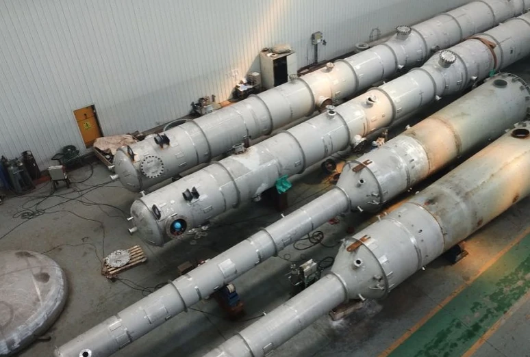
Towers are similar to vertical process vessels in that they are erected vertically and they are cylindrical in shape with heads at each end of the cylinder. Towers are, however, normally much taller then vertical process vessels. Typically the length to diameter ratio of a tower ranges from 3:1 to 20:1. Towers typically range in diameter from 3 to 20 FEET and in height from 20 to 150 FEET.
Tower/Column Applications
Towers are commonly used for the following purposes:
Distillation
Stripping
Absorption
Adsorption
Extraction.
A description of these items follows.
Distillation — Distillation is a process which separates a mixture of materials into two or more desired parts. The device which performs this operation may be called a distillation tower, distillation column or fractionator. The operation of a distillation column depends on the fact that different materials boil at different temperatures. For example, water boils at 212 DEG F and ethyl alcohol (the active ingredient in liquor) boils at 173 DEG F. Distillation is not a new concept. The material which boils at the lower temperature is called the light or more volatile component. The material with the higher boiling point is called the heavy or less volatile component. In the case of ethyl alcohol and water, we are dealing with a two component or binary mixture. This is not the usual case. More commonly, the feed to a distillation column is a multi-component mixture. For example, crude oil contains hundreds of different components. The purpose of distilling crude oil is to separate it into what are called fractions or cuts. Each fraction or cut is not a pure component, but a mixture of components which may be used as is or refined further. Crude distillation normally is used to produce these fractions: raw gasoline, raw kerosene, gas oil and reduced crude.
Stripping — The process of extracting a material dissolved in a liquid phase and transferring it into a gas phase is called stripping or desorption. The stripping process is carried out in a device called a stripping tower or stripping column. The removal of ammonia from water is an example of the stripping process. Water with ammonia dissolved in it passes down the stripping tower. Air passing upward through the tower strips the ammonia from the water and the ammonia - air mixture exits from the top of the tower.
Absorption — The process of transferring a material from the gas phase to the liquid phase is called absorption. The liquid into which the gaseous component dissolves is called the absorbent. The device in which the absorption process takes place is called an absorption tower, absorption column or absorber. The removal of carbon dioxide and hydrogen sulfide from the natural gas with deithanolamine (DEA) is an example of the absorption process. Natural gas, CO2 and H2S pass upward through the tower. DEA passing downwards absorbs the CO2 and H2S.
Adsorption — The process of transferring a material from either the gas or liquid phase to the solid phase is called adsorption. The solid to which the liquid or gaseous component attached itself is called the adsorbent. The device in which the adsorption process takes place is usually called an adsorption tower, adsorption column or adsorber. If the purpose of the adsorber is to remove water, the term drying tower or dryer is often used.
Extraction — The process of transferring material from one liquid phase to another immiscible liquid phase is called liquid - liquid extraction, solvent extraction or simply extraction. Immiscible liquids are liquids which do not dissolve in each other, or example, oil and water. If the two immiscible liquids are contacted countercurrently, the contacting device is called an extraction column, extraction tower or extractor.
Tower/Column Internals
Trays — Trays may be divided into two major categories; crossflow trays and counter flow trays. Crossflow trays get their name because liquid flows across the tray to a downcomer while vapor rises through perforations in the tray deck. There are three types of crossflow trays in common use today. They are the bubble cap, sieve tray, and valve tray. The bubble cap trays were used almost exclusively until about 1950. Since then, the use of bubble cap trays has almost disappeared because their complicated construction makes them heavy (resulting in heavier and more expensive tray supports) and expensive to fabricate.
Bubble cap trays get their name because vapor rises through holes in the tray and is collected underneath bubble caps. Each cap has slots in it through which the vapor from the tray below bubbles into the liquid on the tray.
Sieve trays are the cheapest trays to fabricate because of their simple design. They consist of a perforated plate through which vapor rises from the tray below, a weir to hold a liquid level on the tray, and a downcomer which acts as a downspout to direct the liquid to the tray below. The operation of the sieve tray depends on the vapor velocity through the perforations being high enough to keep the liquid flowing across the tray and not down through the same perforations the vapor is rising through. The drawback to the sieve tray is that it has a narrow operating range compared to the bubble cap tray and the valve tray. Too low a vapor velocity and the liquid falls through the holes to the plate below - a condition called dumping. Too high a velocity and vapor doesn’t bubble through the liquid on the tray. Instead, the vapor pushes the liquid away from the hole so that there is no liquid-vapor contact. This condition is called coning.
Valve trays have liftable caps which operate like check valves. These caps make valve trays more expensive than sieve trays but they also increase the operating range of the tray. At low vapor velocities, the caps close and prevent dumping. The other major category of trays is the counterflow type. These trays have no downcomers. The liquid falls through the same openings in the tray that the vapor from the tray below rises through. This type of tray is not widely used. The most popular of the counterflow type tray is the Turbogrid tray.
Packings — The second major category of tower internals is packings. Packings serve the same purpose as trays; they bring a gas or vapor stream into intimate contact with a liquid stream. Trays accomplish this by providing a very large wetted surface area for the gas or vapor to flow by. Packed towers would normally be selected instead of tray towers in the following instances:
For columns less than 2 FEET in diameter, packing is generally cheaper.
If highly corrosive fluids are being handled, packings are often advantageous because they can be made of ceramic, carbon, plastic or other highly resistant metallic or non-metallic material.
Packed towers are low pressure drop devices, therefore, they are often used for vacuum distillations.
The major disadvantages of packed towers are:
They have a narrower operating range than tray towers.
A packed tower must have a larger diameter than a tray tower to handle the same feed rate.
The most common types of packings are: Rashig rings, Berl saddles, Intalox saddles and Pall rings.
Adsorption towers are packed towers; however, their function is to transfer a material from the liquid or gas phase onto the surface of the solid adsorbent. Adsorbents are not packing types.
Adsorbents are generally either a granular material or else spherical or cylindrical shaped pellets. Some common adsorbents are: Fuller’s earthes (natural clays), activated clay, alumina, activated carbon and silica gel.
Materials of Construction
The tower shell and heads are usually fabricated out of carbon or low alloy steel plate.
As the name implies, the primary alloying element in carbon steel is carbon. All the other alloying elements in carbon steel are limited to concentrations less than 0.5%. The most common materials of construction for towers are the carbon steels A515 and A516.
Low alloy steel contain one or more alloying elements besides carbon in concentrations from 0.5% to 10%. Alloying elements in concentrations greater than 10% make the steel a high alloy steel.
When extremely corrosive materials are to be handled, the tower may be fabricated out of a high alloy steel such as one of the stainless steels, a non-ferrous metal such as titanium or monel, or a non-metal such as FRP (fiberglass reinforced polyester). However, because these materials are either very expensive or else have design limitations such as low strength, claddings and linings are commonly used for corrosion resistance. Clad plate consists of a thin layer of corrosion-resistant metal permanently bonded to an inexpensive carbon or low alloy steel backing. Linings differ from claddings in that there is not a permanent continuous bond between the corrosion-resistant material and the backing material, and the corrosion-resistant material is usually not a metal. Common lining materials are brick, cement, rubber and glass.
Shell and Head Design
Typically, many companies normally require that tower shells and heads be designed according to the latest edition of Section VIII Division 1 of the ASME Boiler and Pressure Vessel Code. Towers manufactured in the United States will carry the ASME code stamp certifying that the vessel has been designed and fabricated to code standards. Towers manufactured outside the United States are to be designed and fabricated according to code standards as well, but need not carry the code stamp.
Towers that are unusually large, or towers which are required to operate at a very high pressure may be designed according to Section VIII Division 2 of the ASME Code. Division 2 requires complete stress analysis of the process vessel. This complete analysis allows the vessel to be designed with much smaller safety factors. This results in a vessel which has a thinner shell and head and is therefore cheaper to fabricate than the same vessel designed according to the rules of Division 1. Since a Division 2 design results in a cheaper vessel, why aren’t all process vessels designed according to the rules of Division 2? Again it is a question of economics. A Division 2 design is so complex that the money spent in extra engineering time for the vessel can easily exceed the savings realized in the fabrication of the vessel. Only in very large or thick-walled vessels is the economic advantage of Division 2 clear-cut.
Conclusion
“Towers” and “columns” are interchangeable name for the same device. These devices have one of two functions. One is to separate a mixture into two or more desired parts. The other function is to transfer a material from one phase to another phase.
Towers are classified according to the function performed. Examples are distillation, stripping or extraction. Towers are also classified by the type of device installed inside (internals) so the tower can perform its desired function. Tower internals consist of either trays or packings.
Towers are always erected vertically. They are usually tall and cylindrical in shape. Sometimes they are designed with the top of the tower one diameter and the bottom a different (usually larger) diameter. This gives the tower a “Coke bottle” shape and is called a double diameter tower.
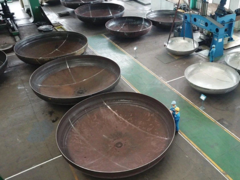
The cylindrically shaped body of the tower is called the shell. The shell is closed at both ends with dome-shaped covers called heads. There are three head designs in common use:
Torispherical, the most common of which is the ASME flanged and dished head
Ellipsoidal, also called elliptical, elliptical dished or 2:1 ellipsoidal (because the ratio of the length of the major to the minor axis of this head is 2:1)
Hemispherical.
Which kind of head to use is an economic decision. The torispherical head is the cheapest to fabricate, but is the thickest for a given pressure. The ellipsoidal head is more expensive to fabricate than the torispherical, but is thinner at the same pressure. The hemispherical head is the most costly to fabricate, but is the thinnest for a given pressure. Thus, the material cost decreases from the torispherical to hemispherical because the head gets thinner, but the fabricating costs increase. At pressures below 150 PSIG the torispherical head is generally the cheapest. From 150 PSIG to 500 PSIG, the ellipsoidal is usually selected. Above 150 PSIG, the hemispherical head becomes an economically viable alternative.
Openings are provided in the shell and heads of a tower so that process fluids can enter and leave. Other openings in the tower are provided for drains, purge connections and sample connections. These openings into the tower are called nozzles. Nozzles range in diameter from 1 INCH for small drains, vents and sample connections to 24 INCHES [1,200 MM] or more for large process connections. The small (1 INCH) connections are usually made with pipe couplings, not with welding necks and flanges.
Workers must be able to enter the tower after it is erected to install and maintain the internals. Openings in the tower provided for this purpose are called manholes or manways. Manholes are just nozzles large enough for a man to pass through. Manholes range in diameter from 18 - 24 INCHES [1,200 MM].
A tower is normally supported by a steel cylinder the same diameter as the tower called a skirt. The skirt is welded to the tower at one end and bolted to the foundation at the other.
In addition to nozzles, manholes and skirts, other appurtenances may be attached to the tower. These other externals may include insulation clips for the support of insulation, lifting lugs which are eyelets to which rigging is attached so that the tower can be lifted and placed on its foundation, and various structural steel members for the support of platforms and ladders.
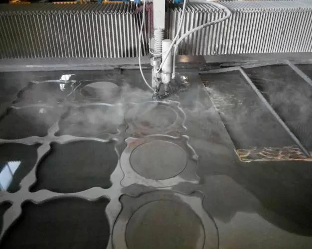
Water cutting, also known as water jet cutting, is a high-pressure water jet cutting technology, which is a machine that uses high-pressure water jet cutting. Under the control of the computer, the workpiece can be carved arbitrarily, and it is less affected by the texture of the material. Because of its low cost, easy operation, and high yield rate, waterjet cutting is gradually becoming the mainstream cutting method in industrial cutting technology.
Waterjet cutting uses a high-pressure stream of water mixed with an abrasive material to cut a wide range of materials.
A high-pressure water pump pressurises the water. This water flows through high-pressure tubing into the cutting head. In the cutting head, the water flows through a nozzle, turning it into an extremely fine stream. This stream cuts whatever material is placed in front of it.
A waterjet cutting machine can produce pressures as high as 100,000 psi or about 6900 bars. To put it into perspective, fire hoses generally deliver pressures between 8 to 20 bars. The waterjet nozzle is assisted by a vision system to facilitate the precise and efficient cutting of the part.
It is easy to manipulate the nozzle to accommodate the cutting of different materials. Depending on whether an abrasive substance is used or not, there are two types of waterjet cutting methods: Abrasive waterjet cutting and Pure waterjet cutting.
Abrasive waterjet cutting
When cutting harder materials, abrasive agents are mixed with the water. This occurs in a mixing chamber located in the cutting head just before the abrasive jet exits the system.
Popular agents for abrasive waterjet cutting are suspended grit, garnet and aluminium oxide. As the material thickness/hardness increases, so should the hardness of the abrasives in use.
With the right abrasives, various material types can be cut. Common materials cut with abrasives are ceramics, metals, stones and thick plastics. There are, however, certain exceptions such as tempered glass and diamonds that cannot be cut with abrasive water. Tempered glass shatters when cut with a water jet.
Pure waterjet cutting
Water jet cutters also work without the addition of abrasives, mainly to cut soft materials. A waterjet cutter designed only for this purpose does not have a mixing chamber or a nozzle. A high-pressure pump forces pressurised water out of an orifice to create precise cuts on the workpiece. Although most industrial cutting devices using waterjet technology enable the use of both methods.
Pure waterjet cutting process is less invasive compared to abrasive waterjet cutting. The jet stream is also exceptionally fine and does not impart any additional pressure on the workpiece.
Pure waterjet cutting is ideal for softer materials like foam, felt, wood, rubber, food and thin plastics.
Waterjet Cutting Materials
Waterjet cutting can cut almost all materials. The process is compatible with a wide range of materials like:
Metals
The high velocity and pressures in waterjet systems make them capable of cutting thin and thick metals with relative ease. This process is capable of cutting extremely hard materials such as titanium and inconel along with common metals such as aluminium and mild steel.
The process is mainly used to cut thicker workpieces that can’t be cut with laser or plasma. For thinner metals, laser cutting has an edge over waterjet in terms of cutting speed. A waterjet cutter with a 30 HP pump can cut 12 mm titanium at a rate of 180 mm/min.
For metals, waterjet provides the advantage of no HAZ formation which improves the final quality of a part significantly. There is also no need for secondary finishing in most cases as this process provides satin-smooth edges.
Waterjet cutting metal parts have high quality and are thus used in the most demanding sectors such as the aerospace industry that have no margin of error.
Wood
A decent waterjet cutting machine can effectively cut wood up to 125 mm in thickness at a rate of up to 15 m/min. It can be used to split wood as well as to carve intricate shapes. Moreover, the stream passes the wood at such a high speed that it causes virtually no surface wetness. This prevents the wood from absorbing the water. The high pressure also causes minimal delamination.
However, the machine may have to be recalibrated if there are knots in the wood. Either we can use a higher pressure that can cut through the knots along with non-knotted areas or use different pressures for different areas. Using either option can affect the final quality of the part.
Rubber
Waterjet technology is also increasingly used to cut rubber with varying thicknesses. A key advantage of a waterjet cutter is that it does not create concave edges, unlike die-cutting.
The technology is also not limited by the thickness of the rubber. The abrasive waterjet machine can cut rubber of varying hardness and thickness to the desired final quality.
In many cases, pure water jet cutting may be enough to meet product specifications for rubber products. Pure water jet cutting can easily cut sponge rubber of up to 50 mm thickness and hard rubber greater than 25 mm thickness up to a bidirectional tolerance of 0.25 mm.
Ceramics
Waterjet technology is commonly used in industrial cutting devices for ceramics. Ceramics are hard and brittle and difficult to machine. They cannot withstand the excessive pressure that a workpiece is subjected to in other mechanical cutting methods.
In waterjet cutting, no excessive pressure is applied to the workpiece except at the cutting point. This makes it ideal for cutting ceramics. The cutter can pierce its own starting hole and precisely cut complex shapes.
CNC (computer numerical control) technology is used in conjunction with abrasive waterjet cutting to ensure repeatable accuracy and good edge quality.
Glass
Waterjet cutting can cut a variety of glass with incredible detail. It can cut the most delicate glass without cracks or craters on it. On the other end of the spectrum, you may use it to cut stained glass.
Cutting with a water jet does not require etching or breaking. But starting holes are pierced at a lower pressure due to the tendency to crack. A waterjet can cut up to 50 mm of bulletproof glass, this number is even greater for other types of glass.
Stone and tiles
Stone and tiles are other common applications for waterjet cutters. With the right technical settings, we can use a waterjet cutter for cement, ceramic, glass, granite, limestone, mosaic, metal, porcelain, travertine and quarry tiles.
Features of waterjet cutting:
Water cutting mainly has the following features:
1. Cold cutting: Because water and abrasive cutting are used, there is basically no thermal effect during processing, and the workpiece will not be deformed by heat and will not change its physical and chemical properties. It is especially suitable for materials that are greatly affected by heat, such as titanium.
2. Wide cutting range: It can cut almost all metal or non-metal materials, such as stainless steel, copper, aluminum, various alloys, ceramics, glass, composite materials, etc., and is not limited by thickness.
3. High cutting precision: the cutting surface is neat and smooth, and will not cause any damage to the object to be cut during the cutting process, and can complete cutting operations that many cutting tools cannot achieve; the slit is extremely small, which can reduce the material waste rate.
4. Good adaptability: high production efficiency, cutting can start from any point on the workpiece and proceed in any direction. Combining with CNC technology, CNC can realize mass production of workpieces with complex shapes. Moreover, one nozzle can process different types of materials and shapes without changing tools, which saves time and cost and improves production efficiency.
5. High safety and environmental protection: No toxic fumes are produced during the cutting process, and there is no spark, no thermal effect, and small vibration. It is a safe and environmentally friendly cutting process, especially suitable for dangerous working environments with special requirements.
Applications of waterjet cutting technology
Waterjet equipment and technology are research hotspots in the waterjet industry in various countries in recent years. According to previous international waterjet conferences, with the commercialization of waterjet equipment and technology, waterjet has been widely used in many industries.
1. Aerospace industry, such as titanium alloy, carbon fiber, special laminated thick glass, plexiglass, honeycomb panel, ceramic insulation layer, special rubber, metal matrix and ceramic matrix composite materials, rocket solid fuel cutting, instrument panel processing, etc.
2. In the military industry, it is used for cutting high-strength steel plates, armor plates, various special decoration materials, armor plates, tracks, turrets, bumpers, artillery, gun xie, bulletproof glass, car bodies, ammunition, etc. of various tanks. Clean up the mines and bombs left over from the war, deal with the explosives created by terrorism and separatist forces, peel off the adhesive layer and ice layer on the runway of military airports, cut nuclear reactors and waste, cut underwater structures and shipwrecks in military ports , military fortifications and engineering rock breaking, etc.
3. In the mining industry, the dust and friction sparks produced by the jet cutting rock are less, making it especially suitable for closed environments, such as underground rock mining. The reduction of dust improves the working environment, and the reduction of friction sparks greatly reduces the possibility of gas explosion during coal mining. The ultra-high pressure water jet reaming equipment for different hardness coal seams and different types of borehole reaming can increase the exposed area of coal around the borehole, increase the pressure relief range and influence radius of the borehole, thereby improving the drainage effect of the borehole .
4. In the automobile manufacturing industry, it is used for cutting instrument panels, interior and exterior decorations, door panels, and window glass without molds, which can improve the processing flexibility of the production line.
5. The building material industry and building decoration industry have technical advantages that other cutting technologies lack. It can be used to cut marble, granite, glass fiber, ceramics, asbestos and other materials, and can also cut complex-shaped stone mosaics. The cutting size is accurate and pollution-free. Water jet cutting technology can be used to remove aluminum oxide on the outside of the workpiece, molding sand and ceramic coating on the casting, and can also cut gray iron castings that are difficult to cut by conventional methods.
6. In the electronics industry, it is used for contour cutting of printed circuit boards, wafer cutting in integrated circuit chip manufacturing and cutting processes in ceramic mosaic technology, etc.
7. In the food industry, it is used to cut crispy food, vegetables, meat, etc., which can reduce the damage of cell tissue and increase the storage period. When cutting food, the "NC water jet" can control its cutting speed and route with a numerical control device, which can maintain the nutritional content of the cut object to the greatest extent, without causing the spread of bacteria and regular shape.
8. In the paper industry, it can be used for coiling and cutting of kraft paper, corrugated box board, etc., without dust pollution.
9. In the field of textile industry, it is used for cutting multi-layer fabrics, improving cutting efficiency and reducing edge damage. Waterjet cutting is also widely used in clothing cutting, shoe blanking, etc. Water jet cutting and effective nesting can save up to 18% of raw materials in shoe blanking.
10. Underwater cutting, the exploitation of seabed oil and solid mineral deposits, and the maintenance of ships and warships all inevitably require underwater cutting technology. Ultra-high-pressure water jet cutting can be used in various occasions such as underwater rescue and underwater repair, salvage operations, underwater demonstration sampling, oil drilling, offshore platform disassembly, wharf construction and maintenance, underwater operations of ships, and marine engineering. With the development and utilization of the ocean, the underwater cutting technology of ultra-high-pressure abrasive water jet is bound to develop rapidly.
11. Harmful and poisonous on-site cutting, in earthquake rescue and post-disaster reconstruction work, ultra-high pressure water jet spray dust reduction and cutting concrete structures, etc. Water jet cutting technology is especially suitable for cutting workpieces in flammable and explosive environments.
Compared with other cutting methods, water cutting has its own unique advantages.
1. vs laser cutting
Laser cutting is a very advanced cutting technology with fast cutting speed and high precision, but its limitation is that it is mostly used for cutting thin steel plates and some non-metallic materials, and it will cause thermal effects at the slit during cutting, which is harmful to aluminum and copper. The cutting effect of non-ferrous metals and alloys is not ideal. For thick metal plates, the cutting speed is slow, or even impossible to cut. Waterjet cutting is suitable for almost all kinds of materials, the cutting thickness is large, there is no thermal effect, and there is basically no limitation of laser cutting. But the cutting speed of water jetting is not as fast as laser cutting.
2. vs plasma cutting
Plasma cutting uses a high-temperature plasma arc to cut. The thermal effect is obvious, the precision is not high, and a large amount of toxic fumes are generated during the cutting process, which is poor in environmental protection. Waterjet cutting belongs to cold state cutting, no thermal deformation, good cutting precision, safety and environmental protection.
3. vs wire cutting
Wire cutting belongs to the category of electrical processing and has high precision for metal processing. The disadvantage is that it can only cut conductive metal materials, and the speed is slow and the efficiency is low. Sometimes it is necessary to punch a process hole in the workpiece in advance to thread the wire. The electrode wire used for cutting is easy to break, and the cutting size is greatly limited. Waterjet cutting is not limited by materials, with fast cutting speed and high efficiency, and a wide range of optional processing sizes.
4. vs other traditional cutting methods
Flame cutting is often used for cutting metal sheets. Compared with water cutting, its thermal effect is obvious, the cutting surface quality and accuracy are poor, and secondary processing is generally required; punching and shearing processing has high efficiency and fast speed, and is generally suitable for large quantities of small pieces. The disadvantage of processing is that it requires specific molds and tools, and it is difficult or impossible to process materials with large thickness and high hardness. Water cutting is not affected by material shape, thickness, hardness, etc., and has better versatility.
Prospects of waterjet cutting technology
The further development of water flow processing technology is mainly in the following aspects.
1. Develop intelligent control. Using high-pressure water jet to process parts with high precision requirements or complex shapes, the production and application of water jet CNC machining machines with more than 5 axes is a necessary prerequisite. This requires a large number of processing experiments to determine the process parameters in different situations, so that the process parameters can be adaptively adjusted during the process, so as to improve the machining accuracy of the machine tool. It is extremely necessary for the design and development of this kind of high-precision water jet processing machine tool, which is directly related to whether the high-pressure water jet technology can meet the practicality of the entire process from rough machining to finishing.
2. Improve processing efficiency. Optimize the process parameters of abrasive water jet processing, further improve efficiency, reduce abrasive consumption and energy consumption, and make the cost of abrasive water jet processing more competitive. Using abrasive water jets to process various difficult-to-machine materials of different materials and cutting of various composite materials, the processing efficiency is still relatively low. Further development of water jet processing technology to improve the processing efficiency and quality of these materials is the focus of future technological development. difficulty.
3. Open up research on new types of jets. Different processing requirements will inevitably require different types of processing capabilities. Different types of high-pressure water jets such as cavitation jets, pulse jets, coolant beam jets, high-viscosity additive jets, magnetorheological fluid jets, and room temperature freezing point jets must have a wider range of applications. Application prospect.
4. Continuously expand the application range of water jet processing. With the research and application of various new materials, the corresponding processing technology must develop rapidly, and the water jet technology will be more and more widely used because of its unique advantages. Water jet technology still has a very broad application prospect in the field of finishing and ultra-precision machining, but the problems that need to be overcome are also extremely difficult.
5. Comprehensive application of other processing technologies. The organic combination of other processing technologies such as laser, ultrasonic, electrolytic processing and high-pressure water jet technology will significantly improve the application range and processing efficiency of water jet technology.
It is inevitable that the laser cutting equipment will break down during use. The following points are our summary of common failures and solutions of laser cutting equipment.
I, No laser during work
First, check whether the laser tube itself emits light (test at the light outlet);
Check whether the water circulation is normal (see whether the water flow in the water pipe is smooth), if there is no water flow or the water flow is not smooth;
The water circulation is normal, check whether the power supply fan is rotating, if not;
Press the laser power test button, if there is no light;
If there is light in the test;
If the water protection signal line is short-circuited, there is still no light.
Solutions
Check whether the lens is damaged and whether the optical path is offset;
Clean the water pump and straighten out the water pipes;
If the laser power supply is broken, replace the laser power supply;
One of the laser power supply or laser tube is faulty;
If the water protector is broken, replace it;
If the control card or wiring board is faulty, replace it.
II, There is no action when starting up
Check whether the fluorescent tube of the equipment is displayed or bright, if not;
If the light is on, check the software setting parameters for the new model, if the parameters are wrong;
The parameters are correct, but there is still no action.
Solutions
Check the power supply system or main power fuse;
Write the correct parameters;
The control card or driver is faulty.
III, The machine sometimes has light and sometimes has no light
Check whether the lens is too dirty or damaged, and whether the optical path is seriously shifted;
The optical path of the lens is normal, check whether the water cycle is normal, if the water is intermittent;
The water cycle is normal, which may be a water protection failure;
If the problem persists, the control card, laser light source, and laser tube may all cause this phenomenon.
Approach
Clean or replace the lens, adjust the optical path;
Clean or replace the water pump and dredge the water pipe;
Replace the water protection;
Alternately replace the above accessories to find out the reason.
IV, The engraving becomes lighter
Check the working current, speed, and water temperature. If the speed is too fast, the current is too small, and the water temperature is too high;
Check whether the cutting depth is normal, if normal;
The cutting is still very shallow, or sometimes deep and sometimes shallow;
Look at the ammeter, if it can reach 20mA, but the depth is not enough.
Solutions
Increase the current, reduce the speed, and replace the circulating water;
Increase graphics resolution;
Whether the lens is dirty or damaged, and whether the optical path is offset;
The laser tube is aging, replace the laser tube.
V, The machine stops halfway, misses engraving, and indiscriminately engraves
Check the grounding status of the machine, and measure whether the ground wire is up to standard (the resistance to ground should not be greater than 5 ohms);
Check whether the computer has a screen saver or power saving mode (such as system hibernation or turning off the hard disk) for low-speed and high-speed motherboards;
Check whether there is any error in the original graphics, such as graphics with intersections, unclosed, missing strokes, etc.;
There is no such problem when making other graphics, but only a certain graphic has such a problem;
The problem still exists.
Solutions
Transform the ground wire to meet the relevant standards;
Cancel the above settings and change to "never";
Correct the errors in the graphics;
There is an error in the processing of the new data in the picture, and the effect picture should be re-made;
It may be a problem with the serial port of the computer or the control card of the engraving machine.
VI, The size of the graphics output is wrong
Check whether the pulse equivalent in the machine settings is set correctly.
Solution
Input and set the correct pulse equivalent.
VII, the machine reset is not normal
The direction is correct when resetting, but the laser head and the beam cannot stop when it reaches the fixed point (check the software parameters first for the new machine, if it is correct);
The crossbeam resets normally, but the laser head does not reset. It may be that the tension wheel is stuck or the motor shaft is broken, and the parameters are wrong;
When the GN machine is reset, the trolley moves in the opposite direction to the beam and hits the side end;
When the GN model does not reset, pay attention to whether the 68-core data cable and the adapter board have poor contact or open circuit.
Solutions
The control card and the limit sensor are faulty, replace them;
Replace the tensioning wheel or small motor, and modify the parameters;
If the software parameters are wrong, stop the machine to correct the software parameters;
Re-insert or replace the data cable and adapter board.
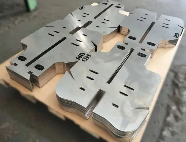
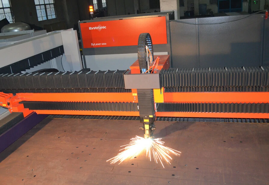
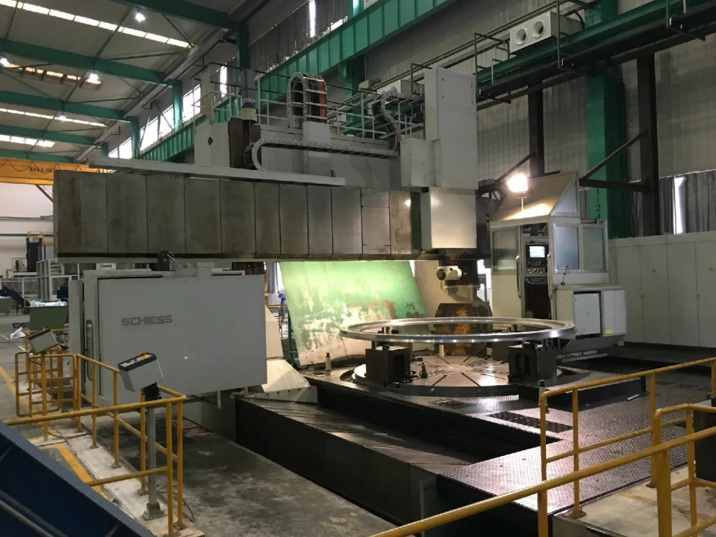
Our cutting capabilities are second to none. We totally have about 154 sets of steel cutting machines including water jet cutting, laser cutting, high definition plasma cutting, robotic contour beveling, flame-cutting, sawing machines from Germany Trumpf, Germany Messer, Japan Tanaka, Japan Koike, Switzerland Bystronic, Sweden WSJ, American FLOW, Italy and so on. Our cutting facilities have some of the longest tables in the fabrication industry. Automated cutting maintains speed and accuracy, while long tables allow for long pieces and versatile loading. We cut all grades of carbon steel, high-strength steel, alloys, specialty metals, and metallic armor. Openex works with customers to find the best cutting solution for challenging projects. We are not only well equipped for cutting long components, but also for forming and assembling.
Contact us at sales3@openex.com.cn or call us at +86 186 5928 0806 to learn how we can help.
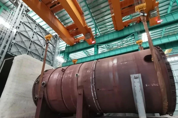
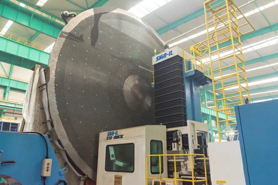
Recently, Openex successfully completed the thermal stress relief of the compound plate equipment with a diameter of 8.6 meters, a length of 21.2 meters and a weight of about 217 tons, marking the formal use of our 36m×12m×13.5m variable volume heat treatment furnace, which also means that our equipment manufacturing capacity has completed a leap.
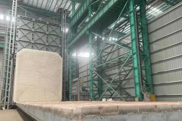
The heat treatment furnace is another tool that we put into use after the vertical ring seam root cleaner. Its effective heating size is 35m×11m×12.5m, and the maximum loading capacity can be 800T.
The heat source of the heat treatment furnace uses natural gas with high calorific value as fuel, and the temperature control precision is ±1℃. The length direction of the heat treatment furnace is divided into three variable volumes: 16.5 meters, 24.5 meters and 36 meters. The heating space is selected according to the size of the equipment that needs heat treatment, which not only improves the equipment manufacturing capacity, but also takes into account energy saving and environmental protection.
Openex's Fabrication Capability:
Openex’s 730,000 square meters manufacturing facility provides ample space for the fabrication, welding, and machining of each custom metal component. Equipped with oxy-fuel and plasma cutting systems, heavy fabrication equipment, manual and CNC machining centers, and overhead cranes capable of handling up to 450 tons. Custom ensures high-quality production of all most all metal structures capable of passing the most strict, non-destructive examination and CMM inspections.
Material Types: castings, forgings, fabricated weldments, billets, bar stock, and plate
Metal Materials we worked: Stainless steel, Carbon Steel, aluminum, brass, bronze, chromium, copper, Monel, nickel, titanium, zinc, and many other superalloys.
Certifications: ISO 9001, 14001,18001, CE EN 1090-1, ISO 3834, ABS, AWS, API, ASME, DNV.GL.
Contact us at sales3@openex.com.cn or call us at +86 186 5928 0806 for more information about fabrication for your industry and to receive a free project quote today.
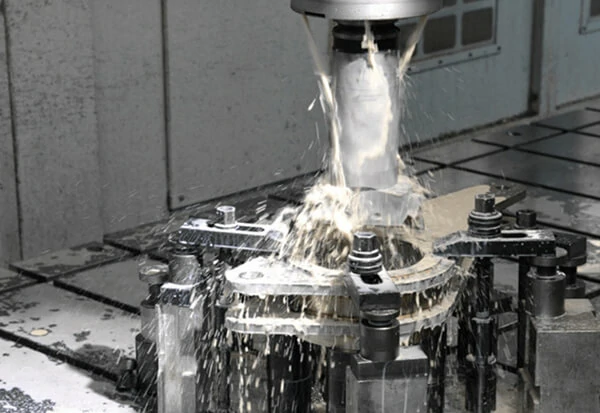
A material removal process in which a sharp cutting tool is used to mechanically cut away material so that the desired part geometry remains
•Most common application: to shape metal parts
•Machining is the most versatile and accurate of all manufacturing processes in its capability to produce a diversity of part geometries and geometric features
Casting can also produce a variety of shapes, but it lacks the precision and accuracy of machining.
What's Machining?
Machining is the broad term used to describe the removal of material from a workpiece. Includes Cutting, Abrasive Processes (grinding), Advanced Machining Processes (electrical, chemical,
thermal, hydrodynamic, lasers)
Automation began when lathes were introduced in 1700s
Now have computer numerical control (CNC) machines
Machining operations are a system consisting of:
Workpiece – material, properties, design, temperature
A single point cutting tool removes material from a rotating workpiece to generate a cylindrical shape. Turning is performed on a machine tool called a lathe.
Boring
Difference between boring and turning:
Boring is performed on the inside diameter of an existing hole
Turning is performed on the outside diameter of an existing cylinder
In effect, boring is an internal turning operation. Boring machines: Horizontal or vertical - refers to the orien
Milling operation in which work is fed past a rotating tool with multiple cutting edges.
Axis of tool rotation is perpendicular to the feed direction
Creates a planar surface
Other geometries possible either by cutter path or shape
•Other factors and terms:
- Milling is an interrupted cutting operation
- Cutting tool called a milling cutter, cutting edges called "teeth".
- Milling tool called a milling machine
Different Tools Used in Different Types of Machining Processes
In a turning tool operation, the workpiece rotates as the tool removes layers from it. The process is similar to boring but reconfigures the external surface of the workpiece instead of the center.
Boring tools:
Boring is the process of enlarging or expanding an existing hole by using a single point cutting tool. It may be used for workpieces that are too large to fit on a lathe or drill press. Standard boring equipment can bore holes up to 12 feet (3.6 m) in diameter.
Drilling removes material using a drill bit to cut a hole of circular cross section in the workpiece. It is the most common machining process, which is used about 75% of the time. A drill jig is placed into a chuck connected to a spindle, which is driven by a drill head powered by a pulley and electric motor. Either electronically or by hand, the drilling tool is lowered onto the surface of the workpiece.
Milling produces three-dimensional shapes using a rotating multi-edge cutting tool. In CNC manufacturing, the milling tool can be programmed to move in several directions on a fixed workpiece. The process can create parts in a wide range of shapes with features such as slots, pockets, and grooves. There are several kinds of milling tools depending on the type of cuts required.
A highly automated machine tool that can perform turning, milling, and drilling operations on a work part
General configuration of a turning center
Can position a cylindrical work part at a specified angle so a rotating cutting tool (e.g., milling cutter) can machine features into the outside surface of the part.
- A conventional turning center cannot stop work part at a defined angular position and does not possess rotating tool spindles.
What Are The Advantages Of Machining?
Reliability
The machining process takes place continuously without any breakdown despite the time or day of the week. The chips and the raw materials are converted into finished products and released into the market as high-quality tools. Breakdowns are very minimal as they may occur when maintenance is required or during a repair. Machines work reliably; it doesn’t matter whether it’s a weekday, weekend, or holiday.
Requires Less Human Labor
Due to the development of technology, machining in manufacturing industries is automated. The process is mainly controlled by computers or robots that usually cut down production costs by eliminating human labor. During the controlled material addition, the process requires minimal supervision and oversight for maintenance purposes.
High Production
The process brings about high productivity because they generally do a massive amount of work such as drilling, better surface finish, milling, and spinning in a relatively short period.
Identical Products
The finished products, such as the cutting metals, are homogenous and have very little or no errors despite the high rate of production. As a result, the products become marketable due to their improved quality.
Increase Profit And Reduce Efforts
Another great reason you need to machine your metal devices is to help increase profits and reduce efforts. Some people may wonder, how does machining relate to increased profits? The fact is that machining makes devices a little expensive, but it is, on the other hand, very beneficial. With a metal that has undergone machining, you will not only reduce the production cost, but it will also save much of your time and effort. Despite this advantage, it is always advisable if you want to purchase one, to be sure to check if the machine is right and whether it is error-free while working.
Improved Efficiency
Machining is one of the best ways that can help increase the efficiency of your metals. When machining the metals, they are always fitted with internal quality assurance detectors. This brings along a lot of efficiency in terms of increasing the speed of production of the metals and ensuring good usage of raw materials. More to this, machining is always considered a remarkable way of ensuring high-level standards of metalworking and part fabrication. More to increase efficiency, machining is considered as one of the ways to cut down expenditure costs. This is due to its ability to drop the consumption cost; therefore, reducing money wastage. In short, it reduces expenditure; thus, adding to the benefits of carrying out the machining process.
Increased Accuracy
Most of the metals that undergo machining are used in the manufacturing industries. This includes places that require manual turning and milling processes. They can also be used in the healthcare sector, but the point you need to note here, all these sectors involve a lot of accuracy. On this, they turn into metals that have undergone machining due to their accuracy level. This is clear evidence of how machining is essential in ensuring increased accuracy on your metals, which translates to accuracy in completing your tasks.
With our large-scale CNC machining capabilities, Openex is a premier provider of quality machined parts and fabrications. Serving the needs of clients from coast to coast, our facility is equipped with large swing lathes, heavy-duty CNC drills, and machining centers that allow us to manage workpieces with oversized dimensions and weighing up to 250 tons. We have a staff of technically skilled machinists noted for their fine quality workmanship and attention to detail on each machining project.
Contact us at sales3@openex.com.cn now for more information about our machining capabilities or a quote.
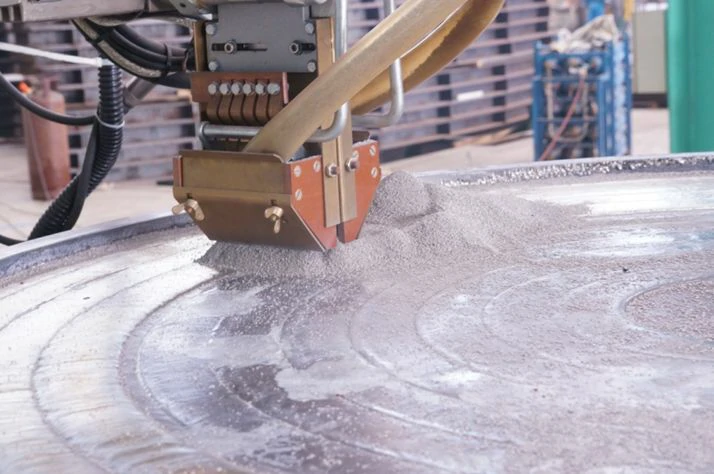
Weld overlay melts one metal—the cladding layer—onto the surface of another metal of similar composition and melting point, forming a base material that is resistant to corrosion and wear. The highly versatile process may require multiple passes to properly mix and bond the metals, while meeting the design and material requirements of the cladding layer.
Customers commonly use weld overlay to balance corrosion-resistant properties and costs, often coating an inexpensive metal, like carbon steel, with a more expensive base layer, such as stainless steel. Our weld overlay process uses readily available metals, reducing lead times, for a wide range of applications, including flanges, fittings, pipes, valves, pressure vessel nozzles and tube sheets for heat exchangers.
Background of Overlay Weld
The deterioration of surfaces is a very real problem in many industries. Wear is the result of impact, erosion, metal-to-metal contact, abrasion, oxidation, and corrosion, or a combination of these. The effects of wear, which are extremely expensive, can be repaired by means of welding. Surfacing with specialized welding filler metals using the normal welding processes is used to replace worn metal with metal that can provide more satisfactory wear than the original. Hardfacing applies a coating for the purpose of reducing wear or loss of material by abrasion, impact, erosion, oxidation, cavitations, etc.
In order to properly select a hard-facing alloy for a specific requirement it is necessary to understand the wear that has occurred and what caused the metal deterioration. The various types of wear can be categorized and defined as follows:
Impact wear is the striking of one object against another. It is a battering, pounding type of wear that breaks, splits, or deforms metal surfaces. It is a slamming contact of metal surfaces with other hard surfaces or objects. A good example is the impact encountered by a shovel dipper lip or tamper.
Abrasion is the wearing away of surfaces by rubbing, grinding, or other types of friction. It usually occurs when a hard material is used on a softer material. It is a scraping or grinding wear that rubs away metal surfaces. It is usually caused by the scouring action of sand, gravel, slag, earth, and other gritty material.
Erosion is the wearing away or destruction of metals and other materials by the abrasive action of water, steam or slurries that carry abrasive materials. Pump parts are subject to this type of wear.
Compression is a deformation type of wear caused by heavy static loads or by slowly increasing pressure on metal surfaces. Compression wear causes metal to move and lose its dimensional accuracy. This can be damaging when parts must maintain close dimensional tolerances.
Cavitation wear results from turbulent flow of liquids, which may carry small suspended abrasive particles.
Metal-to-metal wear is a seizing and galling type of wear that rips and tears out portions of metal surfaces. It is often caused by metal parts seizing together because of lack of lubrication. It usually occurs when the metals moving together are of the same hardness. Frictional heat helps create this type of wear.
Corrosion wear is the gradual eating away or deterioration of unprotected metal surfaces by the effects of the atmosphere, acids, gases, alkalies, etc. This type of wear creates pits and perforations and may eventually dissolve metal parts.
Oxidation is a special type of wear indicated by the flaking off or crumbling of metal surfaces, which takes place when unprotected metal is exposed to a combination of heat, air, moisture. Rust is an example of oxidation.
Corrosion (erosion) wear takes place at the same time. This can happen when corrosive liquids flow over unprotected surfaces.
Thermal shock is a problem indicated by cracking or splintering, which is caused by rapid heating and cooling cycles. While not exactly a wear problem it is a deterioration problem and is thus considered here.
Many of the above types of wear occur in combination with one another. It is wise to consider not only one factor, but to look for a combination of factors that create the wear problem in order to best determine the type of hard facing material to apply. This is done by studying the worn part, the job it does, how it works with other parts of the equipment and the environment in which it works. With these factors in mind it is then possible to make a hardfacing alloy selection.
How to Choose Overlay Weld Metal Material?
There is no standardized method of classifying and specifying the different surfacing weld rods and electrodes. Many of the hard facing electrodes commercially available are not covered by any of most used specifications. Various filler metal suppliers provide data setting forth classes of service and have categorized their own products within these classes. Many suppliers also provide complete information for using their specific products for various applications and for different industries such as quarrying, steel mills, foundries, etc.
The best system of classification has been established by the American Society for Metals Committee on Hardfacing. In this system, there are five major groups classed according to total alloy content other than iron, with subdivisions based on the major alloying elements. Most of these alloys are available as solid bare filler rod in straightened lengths or in coils or covered electrodes. Some of the materials are available as powder for special applications.
The following is a brief description of the five major groups, what they contain as alloys, and where they are recommended.
Group 1 is the low-alloy steels that, with few exceptions, contain chromium as the principal alloying element. The subgroup 1A has alloy content 2-6% including carbon. These alloys are often used as buildup materials under higher-alloy hard facing materials. The Group 1B is similar except that they have a higher alloy content, ranging from 6-12%. Several alloys in the group have higher carbon content exceeding 2%, and include several alloy cast irons. The alloys of Group 1 have the greatest impact resistance of all hardfacing alloys except the austenitic manganese steels (Group 2D) and have better wear resistance than low or medium carbon steels. They are the least expensive of the alloy surfacing materials and are extremely popular. They are machinable and have a moderate improvement over the wear properties of the base metal to which they are welded. They have a high compressive strength and fair resistance to erosion and scratch abrasion.
Group 2 contains higher alloyed steels. Group 2A has chromium (Cr) as the chief alloying element with total alloy content of 12-25%. Many of these alloys also contain molybdenum. Those with over 1.75% carbon are medium-alloy cast irons. Group 2B has molybdenum (Mo) as the principal alloying element but many of these also contain appreciable amounts of chromium. The hardfacing alloys of Groups 2A and 2B are more wear resistant, less shock resistant, and more expensive than those in Group 1.
Groups 2A and 2B are quite strong and have relatively high compressive strengths. They are effective for rebuilding severely worn parts and are used for buildup prior to using higher alloy facing materials. They provide high impact resistance and good abrasion resistance at normal temperatures.
Group 2C contains tungsten and modified high-speed tool steels. They are excellent choices at service temperatures up to 590°C (1100°F) and when good resistance coupled with toughness is required. They are not considered as good high abrasion-resistant types but are resistant to hot abrasion up to 590°C (1100°F) and exhibit good metal-to-metal wear at elevated temperatures.
Group 2D are the austenitic manganese steels, which contain either nickel or molybdenum as stabilizers. The alloys in Group 2D are highly shock resistant but have limited wear resistance unless subjected to work hardening. The total alloy content ranges from 12-25%. This group is excellent for metal-to-metal wear and impact when the deposit is work hardened in use. The as-welded deposit hardness is low, from 70 to 230 BHN, but will work harden to 450-550 BHN. The deposit may deform under battering but it will not crack. The deposit should not be heated to above 260°C (500°F), which would cause embrittlement.
Group 3 contains higher-alloyed compositions ranging from 25-50% total alloy. They are all high-chromium alloys and some contain nickel, molybdenum, or both. The carbon can range from slightly under 2% to over 4%. The alloys in this group exhibit better impact, erosion resistance, metal-to-metal wear, and shock resistance than the previous groups. The 3B grouping will withstand elevated temperatures of up to 540°C (1000°F). The 3C group is high in cobalt which improves high-temperature properties. The Group 3 alloys are more expensive than Groups 1 and 2.
The compositions within Group 4 are nonferrous alloys either cobalt base or nickel base with total content of nonferrous metals from 50 to 99%.
The Group 4A alloys are the high-cobalt-based alloys with high percentage of chromium. These alloys are used exclusively for applications subjected to a combination of heat, corrosion, erosion, and oxidation. They are considered the most versatile of the hard facing materials. The alloys with higher carbon are used for applications requiring high hardness and abrasion resistance but when impact is not as important. These alloys are excellent when service temperatures are above 650°C (1200°F). They resist oxidation temperatures of up to 980°C (1800°F).
The Group 4B alloys are the nickel-based alloys which contain relatively high percentages of chromium. This group of alloys is excellent for metal-to-metal resistance, exhibits good scratch abrasion resistance, and corrosion resistance. They will retain hardness to 540°C (1000°F). The alloys with higher carbon content provide higher hardnesses but are more difficult to machine and provide for less toughness. These alloys show good oxidation resistance up to 950°C (1750°F).
The Group 4C alloys are the chrome-nickel cobalt alloys and all are recommended for elevated temperatures. The high-nickel alloy has excellent resistance to hot impact, abrasion, and corrosion and moderate resistance to wear and deformation at elevated temperatures. The medium-nickel alloy has high-temperature wear resistance and impact resistance. It also provides resistance to erosion, corrosion, and oxidation. The low-nickel alloy is used for moderate high temperatures and provides good edge strength, corrosion resistance, and moderate strength.
The Group 5 alloys provide a tungsten carbide weld deposit. This deposit consists of tungsten carbide particles distributed in a metal matrix. The matrix metals include iron, carbon steel, nickel-based alloys, cobalt-based alloys, and copper-based alloys. The tungsten carbide particles are crushed to mesh sizes varying from 8 to 10 down to 100 and have excellent resistance to abrasion and corrosion, and moderate resistance to impact. The matrix material determines the resistance to corrosion and high-temperature resistance. The finish of the deposit depends on the tungsten carbide particle size: the finer the particles the smoother the finish. The deposits are not machinable and are very difficult to grind.
Types of Overlay Weld Process
To create an effective overlay, providers will match both the materials and the welding technique to the project. To do so, they must consider the goal of the overlay, the properties of the parent metal, and the characteristics of the work environment.
Some of the application options include:
Laser Welding. Typically an automated process, laser welding uses a focused beam of light to quickly melt the cladding into the parent metal. Laser offers high efficiency and excellent results with a smaller heat-affected zone than is possible with conventional arc welding.
Shielded Metal Arc Welding (SMAW). Among the most common welding techniques is shielded metal arc welding, which is more affordable than some other options. It is a manual process that requires the use of a flux-coated consumable electrode. An electrical current creates an arc between the electrode and the metal surface, melting it to join the cladding to the parent metal. The flux melts to create its own shielding gas and produce slag, which adds additional protection to the overlay.
Metal Inert Gas (MIG) Welding. MIG welding is like SMAW welding in that it uses a consumable electrode that melts to form an overlay. However, the electrode does not contain flux, so the shielding gas must be added separately.
Tungsten Inert Gas (TIG) Welding. TIG welding is another shielded arc welding technique, like MIG, but it uses a non-consumable electrode. A separate wire is used to add filler material.
Plasma Transferred Arc (PTA) Welding. PTA welding is an inert-gas process that uses a non-consumable electrode like TIG welding. The major difference is that the cladding material is added directly to the arc as a powder.
Submerged Arc Welding. As its name suggests, submerged arc welding is distinct from other processes because the arc stays hidden—or submerged—beneath the flux blanket. In other respects, submerged arc welding closely resembles SMAW.
A flange is a method of connecting pipes, valves, pumps and other equipment to form a piping system. It also provides easy access for cleaning, inspection or modification. Flanges are usually welded or screwed. Flanged joints are made by bolting together two flanges with a gasket between them to provide a seal.
The Most Used 6 Types of Flanges:
Welding Neck Flange
Slip On Flange
Socket Weld Flange
Lap Joint Flange
Threaded Flange
Blind Flange
Welding Neck Flange
Welding Neck Flanges are easy to recognize at the long tapered hub, which goes gradually over to the wall thickness from a pipe or fitting.
The long tapered hub provides an important reinforcement for use in several applications involving high pressure, sub-zero, and/or elevated temperatures.
These flanges are bored to match the inside diameter of the mating pipe or fitting so there will be no restriction of product flow. This prevents turbulence at the joint and reduces erosion.
This flange type will be welded to a pipe or fitting with a single full penetration, V weld (Butt weld).
Slip On Flange
The calculated strength from a Slip On flange under internal pressure is of the order of two-thirds that of welding neck flanges, and their life under fatigue is about one-third that of the latter.
The connection with the pipe is done with 2 fillet welds, as well at the outside as also at the inside of the flange.
A disadvantage of the flange is, that principle always firstly a pipe must be welded and then just a fitting. A combination of flange and elbow or flange and tee is not possible, because named fittings have not a straight end, that complete slid in the Slip On flange.
Socket Weld Flange
Socket Weld flanges were initially developed for use on small-size high pressure piping. Their static strength is equal to Slip On flanges, but their fatigue strength 50% greater than double-welded Slip On flanges.
The connection with the pipe is done with 1 fillet weld, at the outside of the flange. But before welding, a space must be created between flange or fitting and pipe.
The purpose for the bottoming clearance in a socket weld is usually to reduce the residual stress at the root of the weld that could occur during solidification of the weld metal. The image shows you the X measure for the expansion gap.
Lap Joint Flange
Lap Joint Flanges have all the same common dimensions as any other flange named on this page however it does not have a raised face, they used in conjunction with a "Lap Joint Stub End".
These flanges are nearly identical to a Slip On flange with the exception of a radius at the intersection of the flange face and the bore to accommodate the flanged portion of the stub end.
Their pressure-holding ability is little, if any, better than that of Slip On flanges and the fatigue life for the assembly is only one tenth that of welding neck flanges.
They may be used at all pressures and are available in a full size range. These flanges slip over the pipe, and are not welded or otherwise fastened to it. Bolting pressure is transmitted to the gasket by the pressure of the flange against the back of the pipe lap (Stub End).
Stub End
A Stub End always will be used with a Lap Joint flange, as a backing flange.
This flange connections are applied, in low-pressure and non critical applications, and is a cheap method of flanging.
In a stainless steel pipe system, for example, a carbon steel flange can be applied, because they are not come in contact with the product in the pipe.
Threaded Flange
Threaded Flanges are used for special circumstances with their main advantage being that they can be attached to the pipe without welding. Sometimes a seal weld is also used in conjunction with the threaded connection.
Although still available in most sizes and pressure ratings, screwed fittings today are used almost exclusively in smaller pipe sizes.
A threaded flange or fitting is not suitable for a pipe system with thin wall thickness, because cutting thread on a pipe is not possible. Thus, thicker wall thickness must be chosen...what is thicker ?
Blind Flange
Blind Flanges are manufactured without a bore and used to blank off the ends of piping, valves and pressure vessel openings.
From the standpoint of internal pressure and bolt loading, blind flanges, particularly in the larger sizes, are the most highly stressed flange types.
Flange Faces
Different types of flange faces are used as the contact surfaces to seat the sealing gasket material.
ASME B16.5 and B16.47 define various types of flange facings, including the raised face, the large male and female facings which have identical dimensions to provide a relatively large contact area.
Other flange facings covered by these standards include the large and small tongue-and-groove facings, and the ring joint facing specifically for ring joint type metal gaskets.
Different types of faces
Raised Face (RF)
The raised face flange face is the most common type used in process plant applications, and is easily to identify. It is referred to as a raised face because the gasket surfaces are raised above the bolting circle face
This face type allows the use of a wide combination of gasket designs, including flat ring sheet types and metallic composites such as spiral wound and double jacketed types.
The purpose of an RF flange is to concentrate more pressure on a smaller gasket area and thereby increase the pressure containment capability of the joint
Flat Face (FF)
The flat face flange has a gasket surface in the same plane as the bolting circle face. Applications using flat face flanges are frequently those in which the mating flange or flanged fitting is made from a casting.
Flat face flanges are never to be bolted to a raised face flange.
Ring-Type Joint (RTJ)
This type is typically used in the most severe duties, for example, in high-pressure gas pipe work.
Ring-type metal gaskets must be used on this type of flange facing
The ring-type joint flanges are typically used in high-pressure and/or high-temperature services above 800°F (427°C).
They have grooves cut into their faces which steel ring gaskets. The flanges seal when tightened bolts compress the gasket between the flanges into the grooves, deforming (or Coining) the gasket to make intimate contact inside the grooves, creating a metal-to-metal seal.
Tongue and Groove (T&G):
These flanges feature matching grooves and raised sections. This aids in installation as the design helps the flanges to self-align and provides a reservoir for gasket adhesive.
Male & Female (M&F):
Similar to tongue and groove flanges, these flanges use a matching pair of grooves and raised sections to secure the gasket. However, unlike tongue and groove flanges, these retain the gasket on the female face, providing more accurate placement and increased gasket material options.
Materials for Flanges
Pipe flanges are manufactured in all the different materials like stainless steel, cast iron, aluminium, brass, bronze, plastic etc. but the most used material is forged carbon steel and have machined surfaces.
In addition, flanges, like fittings and pipes, for specific purposes sometimes internally equipped with layers of materials of a completely different quality as the flanges themselves, which are "lined flanges".
The material of a flange, is basically set during the choice of the pipe, in most cases, a flange is of the same material as the pipe.
All flanges, discussed on this website fall under the ASME en ASTM standards, unless otherwise indicated. ASME B16.5 describes dimensions, dimensional tolerances etc. and ASTM the different material qualities.
Advantages and Disadvantages of Flanged Connections VS Welded Connections
There are no standards that define whether or not flange connections may be used.
In a newly built factory is customary to minimize flange connections, because only one weld is needed to connect two pieces of pipe. This saves the costs of two flanges, the gasket, the stud bolts, the second weld, the cost of NDT for the second weld, etc.
Disadvantages
– Each flange connection can leak (some people claim that a flange connection is never 100 percent leak proof).
– Flanged pipe systems need much more space (just think of a pipe rack).
– Insulation of flanged pipe systems is more expensive (special flange caps).
Advantages
– A new line can contain multiple pipe spools and can be manufactured in a workshop.
– This pipe spools can be assembled in the plant without the need to be welded.
– NDO (X-ray, Hydro test etc.) in the plant is not necessary, because this has been done in the workshop.
– Blasting and painting in the plant is not necessary, because even this has been done in a workshop (only paint damages during installation should be repaired).
As with many things, everything has its pros and cons.
What Information Do You Need When Selecting a Flange?
At what pressure will your application be operating?
At what temperature range will your application be operating?
What is your application? Water service? Air Piping? Chemical Piping? Process Piping? High-Pressure Oil or Gas? These questions will likely drive whether you have a pressure requirement.
hat material is required for your application? ANSI and AWWA flanges are most commonly supplied in common carbon steel like A105, however the ANSI B16.5 specification covers a wide variety of materials including high-yield carbon materials, stainless materials and alloys. The AWWA C207 and C228 specifications cover carbon and stainless materials.
Does your application require the welded slip-on, a weld neck flange or a loose backup type lap joint flange?
If you require a weld neck flange, what is the inside diameter/bore size of the pipe you will be welding to?
Are there any specialized gasket requirements? Each flange specification designates the allowable options for gaskets.
Are there any specialized bolt requirements? Each flange specification designates the allowable options for bolting
Other considerations: coating, oil, paint, epoxy, galvanizing
What is your flange mating up with? If your flange mates up to the same type of flange then there are no issues, but if your flange mates up to something else, then understanding the bolt pattern of the existing flange is critical. There are a wide variety of flange specifications, and it will be critical to know what the existing flange spec is so you can assure that the bolt pattern will mate.
Contact us at sales3@openex.com.cn or call us at +86 186 5928 0806 for more information about manufacturing for flanges and to receive a free project quote today.
About Openex
Openex is home to a full-service, one-stop-shop, contract manufacturing company producing custom large machined parts and fabrications. Our full large fabrication services including large machining, cutting, welding, rolling, punching, braking, testing, painting, and others.