We are a custom steel fabricator for the mining industry. We form steel parts and components for mining machines, mining equipment and companies that run mining operations.
We produce components from steel and alloy plates for heavy machinery applications such as heavy-duty front shovel buckets for mining machines, mass excavators, wheel dozers, large heavy-duty bulldozers, wheel loaders, track loaders, and large mining shovels. We form many types of parts that are used to manufacture machines and products used in the surface mining industry. These machines are often used to extract coal, nonmetal minerals such as rock and sand, minerals, ore, metals, rock salt, oil shale, stone, and gravel. Openex fabricates parts made from steel and alloy which are assembled to build surface mining machines such as electric rope shovels. We fabricate dipper buckets, dipper doors, bails, equalizers, and handles. We form and bend heavy steel plates to produce components used to manufacture large hydraulic excavators and hydraulic shovels using in the mining industry. At our factory, we form steel and alloy parts used to make buckets and beams for large front-end loaders. We also form parts used by companies that manufacture draglines, hybrid shovels, mobile mining crushers, surface feeder-breakers, conveyor products and sizers.
Openex is a custom steel fabrication specialist for the mining equipment industry. We have earned an excellent reputation in the mining industry for the quality of the steel and alloy products we build. We understand that high-quality workmanship, meeting delivery schedules and value are important to our customers in the mining industry. Our metalworking experience, custom industrial equipment fabrication services, specialized equipment and heavy steel fabrication capabilities are just a few of the reasons why mining equipment businesses rely on Openex to complete their steel fabrication projects on time.
If your company is in the mining equipment industry and you would like more information or want to get an estimate or quote for custom steel fabrication services, Call +86 186 5928 0806 or email Bell@openex.com.cn.

Key steel fabrication services that we perform for mining equipment companies include CAD design, plate bending, mechanical engineering, manufacturing of wear-resistant components, plate rolling, plate forming, metal forming, cold forming, hot forming, steel plate fabrication, welding, heat-treating, plate cutting and plate straightening. The Company has become a valued supplier of steel and alloy fabrication and design services for the mining industry.
We process a variety of steel and alloy materials for the mining industry including stainless steel, carbon steel, carbon alloy, nickel alloy, aluminum, copper, brass, heat resistant alloys, corrosion-resistant alloys, abrasion resistant alloys, non-ferrous steel and chrome carbide overlay plates.
We provide mine supply operations and mining equipment manufacturers with custom steel manufacturing, metal fabricating, flame cut steel parts, custom equipment and custom component solutions. The quality standards of our close tolerance steel and alloy ASME code fabrications are the highest in the mining industry. Our engineers and fabricators can work from your plans, drawings or CAD designs. We can also provide complimentary design and engineering services to build the parts, components or equipment that meet your specific fabricating requirements. We use a variety of techniques and equipment to complete projects for the mining industry including laser and plasma cutting, heat treating, heavy plate rolling and welding, long press brake forming, contour beveling, and hot and cold forming.
The steel fabrications and heavy machinery components we produce are used in the mining and excavation markets to extract valuable minerals and materials through surface mining and sub-surface (underground) mining.
To get an estimate for custom steel fabrication services for your mining operation or mining equipment manufacturing company, to submit a design or CAD drawing, request a quote or submit an RFQ, ask a sales engineer a question, discuss your current project, place a fabrication order or to schedule a tour of our facilities, Call +86 186 5928 0806 or email yuki.zhou@openex.com.cn. Or, to learn more about Openex’s other products click on any of the following links:
Heavy Machining
Large Fabrication
Tube Sheet Machining
Pressure Vessels Fabrication
Equipment Fabrication
Machinery Fabrication
We are proud to announce the introducing of 3 new CNC laser cutting/chamfering machines into our machine fleet already having been powerful. The new CNC laser cutting machines can cut chamfers from 0 to +/-45° on steel plates with thickness up to 25mm. For the plate parts which need chamfers or blunt edges, Operation only on the same cutting/chamering CNC machine is much more convenient and faster , compared to the usual way that the steel plate after cutting has to be brought to another machine for chamfering.
The newly installed cutting/chamfering CNC laser cutting machine can cut the steel plate with length over 37 m and width over 4.5 m, it will create big value for large scale projects of vessel building and other ones that chamfers are required.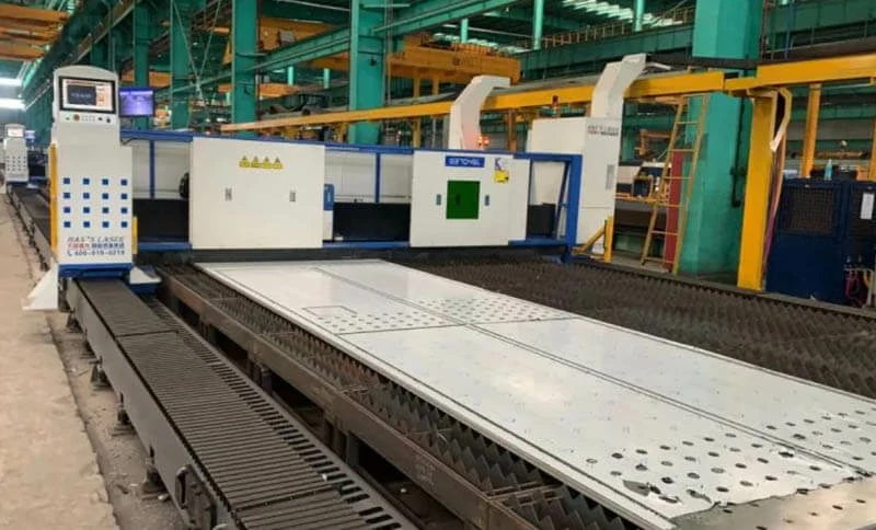

Meeting the needs of mining and mineral processing means creating equipment to stand up to some of the world’s most demanding environments. Openex brings the experience, precision and quality to answer the call.
Extraction, Crushing, Blasthole drilling, Processing, Mining equipment are some of the hardest-working machines on the planet. And when that’s the kind of harsh environment you’re building for, you need a manufacturing partner with the experience and commitment to match. That’s what you can count on from Openex. Fabrication that withstands the toughest of conditions. Industrial gearing with the torque, power and dependability to get the job done. When customers need the most durable, reliable, longest-lasting mining equipment they can get, they turn to Openex.
Whether it’s draglines for surface mining, shovels, crushers, excavators, blasthole drill rigs—Openex can build it. We’ll custom engineer, weld, inspect, machine, refurbish, rebuild and assemble the components that OEMs and their customers depend on for a successful mining operation.
From frame and mast to boom and bucket, Openex will work with you to custom engineer and manufacture the massive dragline equipment that makes surface mining possible. Our team specializes in the large, complex weldments, gearboxes and critical components necessary for dragline excavators, blasthole drill rigs, large dozers and wheel loaders, hydraulic mining shovels, electric rope shovels, large mining trucks, crushing, conveying and material handling and other mining equipment, with a reputation for the greatest durability in the industry.
Precision and Durability at Massive Sizes
We process more than 100,000 tons of steel annually and have the scale and expertise to execute projects of any size with exceptionally attention to detail.
Strong History in Demanding Industries
From mining to heavy construction, infrastructure and power generation, each industry needs equipment that can stand up to punishing work. Openex brings the quality, precision and reliability to meet that challenge.
Unmatched Gear and Gearbox Expertise
From custom design and manufacturing to drop-in replacements, we keep industries moving with precision and performance that withstands even the most demanding applications.
Superior Weld Quality
We’re versed in all major weld methodologies. With essential training and years of experience, we weld massive components with uncompromising quality.

NDE is a general term used to identify all methods that permit evaluation of welds and adjacent areas without destroying their usefulness. Here the following basic NDE methods will be discussed:
It should be noted that NDE does not eliminate the need for destructive testing but rather complements it. The general knowledge presented here should be of valuable assistance to the reader as it provides an overview of the examination methods without unnecessary details.
The integrity of most welds is verified principally by visual examination. Even for weldments with joint specified for inspection throughout by other NDE methods, VT still constitutes an important part of practical quality control. The most extensively used of any method of NDE, VT is easy to apply, quick, and often requires no special equipment other than good eyesight and some relative simple and inexpensive tools.
Despite the many advantages of VT, a major disadvantage is the need for an inspector who has considerable experience and knowledge in many different areas which encompass visual welding examination. The inspector must be familiar with materials, drawings, codes, specifications, weld procedures, performance qualification, procedure qualification requirements, and workmanship standards, and all aspects of good shop practice. Some codes and specifications require that the welding inspector be qualified and certified by examination.
Certain tools are sometimes necessary for some aspects of VT. Various measuring scales and gauges are used for checking the dimensions of the welds. There are many different types of fillet weld gauges used to determine the size of fillet welds. Other gauges can be used to verify root opening, weld reinforcement, and weld bevel angle. Measuring devices are used to check root openings, clearance dimensions of materials, backing materials, and alignment and fit-up of the work pieces. Temperature indicators verify preheat and interpass temperatures. Borescopes, video scopes, flashlights and mirrors are used in areas of limited accessibility. The development of flexible fiber optic inspection systems enables the inspector to visually inspect areas inaccessible to other devices.
PT is a sensitive method of detecting and locating discontinuities, provided the discontinuities are clear and open to the surface. The method employs a penetrating liquid dye which is applied to the properly cleaned surface to be examined and which enters the discontinuity. After a suitable swell time, the excess penetrant is removed from the surface and the part is dried. A developer is then applied which acts as a blotter, drawing the penetrant out of the discontinuity. The penetrant drawn from an opening on the surface indicates the presence and location of a discontinuity.
There are two basic classification of the penetrant method, both using a similar principle. One uses a visible dye and the other uses a fluorescent dye which is only visible with exposure to UV light. Visible penetrant is usually red in color to provide a contrast against the white developer background. Normal white light is usually sufficient to view the discontinuities.
Fluorescent penetrants provide a greenish yellow indication against a dark background when viewed in darkened area under a black (ultraviolet) light source. The fluorescent method is inherently more sensitive due to the fact that human eye can more easily discern a fluorescent indication.
PT is widely applicable on magnetic and non-magnetic materials, but it is particularly useful on nonmagnetic materials such as aluminum, magnesium, and austenitic stainless steels where MT examination cannot be used. It is also useful for locating cracks or other discontinuities which may cause leaks in containers and pipes.
There are two common methods of recording a PT indication for evaluation. A photo may be taken of the discontinuities exposed by the examination. Another method involves the application of clear plastic tape over the indication. When the tape is lifted off the test surface, the indication will adhere to the tape and may be transferred to the inspection report for future reference. These techniques also apply to MT method.
PT method is relatively inexpensive. The process is simple and the operators find little difficulty in learning to apply it properly. The success of this method, like most other examination methods, depends on the visual acuity of the inspector. It should be pointed out that some substances in penetrants can have deleterious effect on either welds or base metals and can affect the service life of the weld or application of the product. Penetrants are difficult to remove completely from discontinuities, and if corrosive to the material, or otherwise not compatible with the product application, they should be avoided.
This method is used for locating surface or near surface discontinuities in ferromagnetic materials. MT is based on the principles that magnetic lines of force will be distorted by a change in material continuity, i.e. discontinuity creating a magnetic field or flux leakage.
A weldment can be magnetized by passing an electric current through the weld area (direct magnetization) or by placing the weldment in a magnetic field (indirect magnetization). When the magnetic field has been established within the workpiece, magnetic particles (medium) are applied to the surface to be examined. The magnetic particles can be dry or suspended in a liquid. Discontinuities can be further enhanced using fluorescent magnetic particles and observing them under black light. After removal of excess particles, the remaining particles trapped in the leakage field of a discontinuity reveal the location, shape, and size of a detectable discontinuity. These indications usually are distinguished by their appearance as sharp, well defined lines of medium against the background of the weld or heat-affected zone surface.
MT can be very beneficial as an in-process evaluation technique. Assurance of a sound weld before the weld is completed may prevent costly repair of the final product. In-process MT has become more of a common practice due to the portability of modern lightweight equipment. This advantage aids in reducing production time.
The cost of MT is considerably less expensive than radiography (RT) and ultrasonic (UT) – both in terms of the equipment cost and the cost of training the personnel. Using MT, the inspector obtains an instant visible indication of the size and orientation of the discontinuity, and allows the inspector to judge if the discontinuity is acceptable or rejectable. Compared to PT, this method has the advantage of revealing discontinuities that are not open to the surface, and therefore not detected by PT. MT is generally faster, requires less surface preparation, and is therefore usually more economical than PT (neglecting equipment costs).
The MT method is limited to ferromagnetic materials. Welded joints made between metals of dissimilar magnetic characteristics may create irrelevant magnetic particle indications even though welds themselves are sound. Most weld surfaces are acceptable for MT after the removal of slag, spatter or other extraneous material which may mechanically hold the test medium.
RT is a method of NDE that utilizes radiation to penetrate a weld and reveal information about its internal condition. When a weld is exposed to penetrating radiation, some radiation will be absorbed, some scattered, and some transmitted through the weld onto recording device (See Figure 13). Most conventional RT techniques used today involve exposures that record a permanent image on a photographic film, although other image recording methods are also used.
The basic process of radiographic examination involves two general steps:
The essential elements needed to carry out these two operations are:
Two types of radiation sources commonly used in weld inspection are X-ray machines and radioactive isotopes. X-radiation is produced by machines which range from portable, low energy units capable of radiographing relatively thin objects, to mammoth linear accelerators and betatrons capable of radiographing thick steel welds up to 20 in. of steel. Gamma radiation is emitted by radioisotopes, the two most common being Cobalt 60 which will penetrate to approximately 5 in. of steel, and Iridium 192 which is limited to a steel thickness of approximately 3 in.
The radiographic process is dependent upon varying amount of radiation being absorbed by different areas of the weld. The differences in the absorption occurring during the exposure process account for the dark and light regions on the radiograph. The interpretation of a radiograph involves identifying the images resulting from various light and dark regions on the film. The dark regions represent the easily penetrated parts of the weld (i.e., thin sections and most discontinuities) while the lighter areas represent the more difficult areas to penetrate (i.e. thick sections).
A significant limitation of radiographs is that discontinuities must be favorably aligned with the radiation beam to be reliably detected. This is usually not a problem for discontinuities such as porosity or slag since they are usually round in cross-section and align with a beam from any direction. This is not the case with planar discontinuities such as cracks, incomplete fusion, and laminations. There are several other limitations associated with radiography:
However, there are some advantages as well:
UT is becoming one of the most widely used methods of NDE. Its primary application is the detection and characterization of internal discontinuities. It is also used to detect surface discontinuities, to define bond characters, and to measure thickness. In this method, high-frequency sound waves are introduced into the material to detect surface and subsurface discontinuities. The sound waves travel through the material with some loss of energy (attenuation) and are reflected at interfaces. The reflected sound beam is detected and analyzed to define the presence and location of discontinuities.
UT is usually performed with either longitudinal waves (straight beam) or shear waves (angle beam). In longitudinal beam testing (commonly used to examine plate material), sound in the form of ultrasonic vibrations is introduced into part perpendicular to the entry surface by straight beam search unit. When the entry surface and the back surface are parallel, a back reflection will appear on the display screen. A discontinuity lying between the front and back surfaces will also be displayed on the display screen. By measuring the height of the reflection on the display screen, from a real or artificial discontinuity of a known size, a reference level can be established such that reflections from discontinuities of unknown sizes may be evaluated.
The angle beam technique is used for the examination of welds. Ideally, only discontinuities should appear on the display screen during the angle beam inspection. This is not always the case, however, since the geometrical boundaries of the part often reflect sound in same manner as a discontinuity. Therefore care must be taken during UT of joints with complex geometries (such as welds with backing bars) to assure that the indications are the result of the presence of discontinuities and not simply due to the configuration of the joint.
It is generally desirable to have the sound beam intercept the plane of the discontinuity at or near 90o so that the maximum amount of sound is reflected to the transducer. However, cracks that are not oriented perpendicular to the UT beam can be detected because their surfaces are not smooth and sound is reflected from the facets that are approximately perpendicular to the beam. Selection of test surface for scanning with the search unit depends upon accessibility. Scanning surface selection is also based on the weld shape and structure. Since it is important to intercept the discontinuity at or near 90o, it is common for more than one angle unit to be used to examine a particular weld.
The principal advantages of UT over other NDE methods for metal parts are:
Some disadvantages of UT include:
Table 2 relates the examination methods to various types of discontinuities. Table 3 relates the joint types to the applicable NDE methods.
| Inspection Methods | |||||||
| Discontinuities | RT | UT | PT | MT | VT | ET | LT |
| Porosity | A | O | A | O | A | O | A |
| Slag inclusions | A | O | A | O | A | O | O |
| Incomplete fusion | O | A | U | O | O | O | U |
| Incomplete joint penetration | A | A | U | O | O | O | U |
| Undercut | A | O | A | O | A | O | U |
| Overlap | U | O | A | A | O | O | U |
| Cracks | O | A | A | A | A | A | A |
| Laminations | U | A | A | A | A | U | U |
Notes:
Legend:
| Inspection Methods | |||||||
| Joints | RT | UT | PT | MT | VT | ET | LT |
| Butt | A | A | A | A | A | A | A |
| Corner | O | A | A | A | A | O | A |
| Tee | O | A | A | A | A | O | A |
| Lap | O | O | A | A | A | O | A |
| Edge | O | O | A | A | A | O | A |
Legend:
This is presented to you as a service from Openex Mechanical Technology Ltd. Since 2009, Openex has been a respected custom large fabrication & heavy machining service supplier. We take pride in our ability to take the most stringent specifications and requirements to provide a high-quality solution to our customers.
Openex is available for shop tours and Pressure Vessel and Static Equipment Fabrication Classes. Please contact: Bell bell@openex.com.cn +86 186 5928 0806
Stainless steel is the leading metal in environmental manufacturing. Compared to others, it's considered one of the most environmentally friendly for use in construction because of its favorable rankings with high recycled content, the potential for product reuse, durability, maintenance requirements, impact on energy and water consumption, and influence on indoor quality and light.
Openex specializes in stainless steel jobs, and we're prepared to meet all of your manufacturing needs, whether it's individual components or entire machine systems, at competitive pricing. We’re experts in ensuring high-quality standards with stainless steel.
Environmental manufacturing is creating products through economically-sound processes that minimize environmental impact; it conserves energy and natural resources. By using environmental manufacturing processes, we can enhance employee, community, and product safety.
Other facets that make stainless steel a very environmentally friendly product: it's 100 percent recyclable with no reduction in quality, has a high scrap value, and its recyclability means it is diverted from landfills and recaptured for new use. On average, the stainless steel recycled content rate is 60 percent. Because the U.S. utilizes more stainless steel, recycled contents can be higher.
Thanks to its high-recycled content and reuse rate, stainless steel plays a significant role in resource conservation. This environmentally manufactured product provides alternative energy equipment, as well as the generation of solar, biomass to energy, nuclear, geothermal, and wave energy power. When air scrubbing systems are made with stainless steel, they make existing energy production cleaner.
The extensive use of stainless steel in public water and sewerage treatment facilities helps store and transport potable water, thus minimizing environmental loss and cleaning wastewater. Stainless steel is being increasingly used for onsite water storage, treatment, or filtration units, allowing for the reduction of potable water consumption.
Another benefit of stainless steel is its ability to reflect solar energy from its surface or high solar reflective index (SRI) value. This feature helps to reflect and dissipate heat away from high slope roofing, wall, and sunscreen panels, thus reducing air conditioning and other energy consumption requirements.
When stainless steel is properly selected, fabricated, and maintained, it can last over centuries. Stainless steel does not need a coating that has to be reapplied or a finish that deteriorates over time. In architectural projects, stainless steel can last up to 80 years without appearance deterioration or metal replacement.
Additionally, stainless steel is a sustainable choice because it produces no VOC emissions. This attribute is essential in buildings where interior air quality control is critical. Steel can be thoroughly steam sanitized and is unlikely to perforate duct walls due to corrosion.
Stainless steel is also a great option for its scratch and impact-resistant qualities. Just as remarkable is its ability to be cleaned thoroughly without damage or the use of environmentally hazardous or dangerous chemicals, which makes it ideal for public use.
If you're looking for any type of metal fabrication or environmental manufacturing in stainless steel, consider Openex's expert service in meeting all of your needs.
Contact us at bell@openex.com.cn today to learn more about our environmental manufacturing service and the other services we offer.
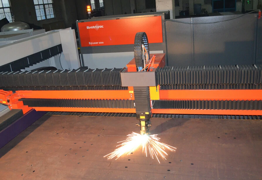
The use of laser technology has become synonymous with precision, and for good reason. Laser cutting, for example, is accurate and versatile, able to produce nearly any shape in a variety of metals. Its range of unique attributes surpasses waterjet cutting, die cutting, and other thermal methods, proving transformative in industrial manufacturing.
Laser cutting is mainly a thermal process, in which the energy from a thin, focused laser is used to cut, melt or burn material. Controlled through computer coding, the cuts are completed to design specification by directing pressure and an amplified beam of light via a nozzle.
Below we’ve explained the four most notable hallmarks of laser cutting and how it can be a benefit to your unique metal fabrication project.
Part Accuracy
Accuracy is one of the primary advantages of laser cutting.
The laser cutting process is almost entirely automated, with programming completed through the use of CNC CAD/CAM technology. This ensures the same cuts can be performed as many times as necessary, with the part matching the blueprint in every instance. And with the laser effectively melting, vaporizing or burning everything in its path, the process also creates clean edges and a smooth finish.
Laser cutting is often used in the packaging, mining, pollution control, and product filling industries in which tight tolerances and strict quality standards are of the utmost importance.
Cut Speed
Laser cutting delivers exceptional speed compared to waterjet cutters and other thermal cutting methods like plasma or flame cutting. Typical speeds for a laser cutter are up to 10 meters per minute, exponentially faster than the range of traditional technologies, which varies from .25 to 2 meters per minute. Fast cutting speeds also minimize heat diffusion into the surrounding material, greatly reducing the potential for thermal damage to other components.
Beyond its speed, laser cutting accelerates the metal fabrication process in other ways:
-Multiple parts can be programmed and cut at once.
-Hard tools aren’t needed, shortening setup time.
-Cutting heads don’t need to be exchanged.
-No additional cleanup is required, eliminating secondary operations.
-Equipment setup and repurposing is expedient, making it easy to adapt to changing project demands.
Puzzle Cutting for Locating Weldment Parts Quickly & Easily
The precision of laser cutters makes them suitable to complete puzzle cuts, a technique used to skip the need for measuring parts when aligning them for a weld. Lasers cut small notches into the sections so they interlock when set together, not unlike the pieces of a puzzle. Once set, a fabricator can tack weld the pieces into place.
Openex uses lasers to complete highly-accurate cuts on stainless steel, aluminum and mild steel. Contact us today to learn more about the our laser capabilities or to request a production quote.
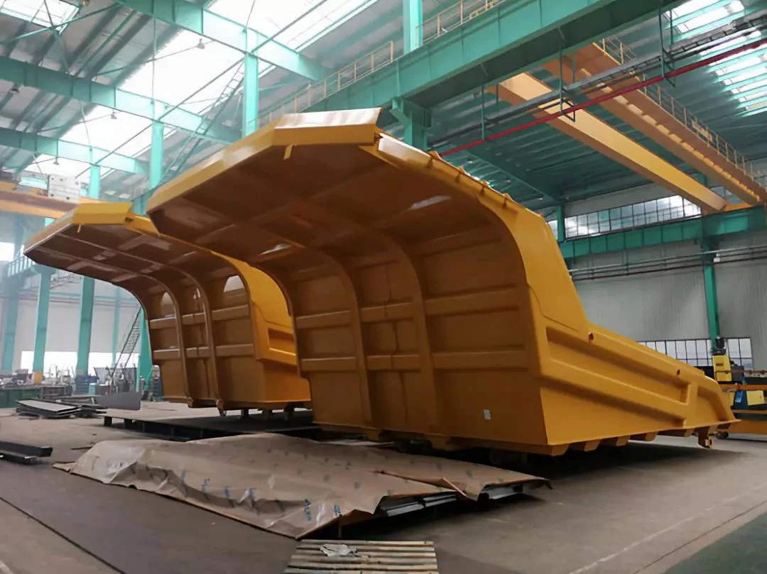
Quantity: 12 sets
Standard: ISO, AWC
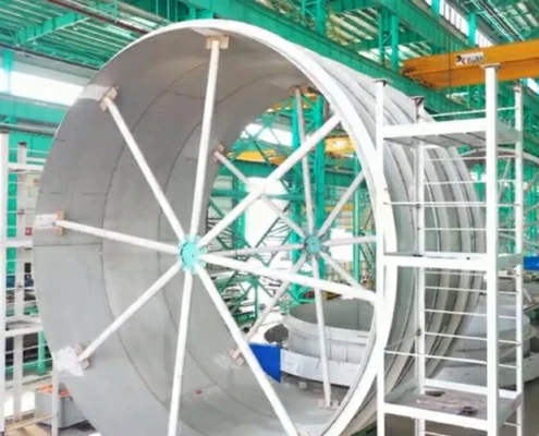
The features of this batch of dump bodies:
-Special-grade steel bolsters, ribs, and structural components for increased durability
-Optimised welding for improved structural integrity
-Maximised payload potential to suit gross vehicle weight for the lowest cost per tonne
-Highly refined design proven to reduce hang up
-Superior load stability and operator comfort for improved safety
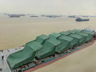
At present, the dump bodies have already been delivered to the customer from Australia.
Openex has rich experiences in dump body fabrication. Except for this mining truck dump body which can be bearing 150 tons, we also fabricated dump bodies bearing 300 tons for customers.
Contact us at sales3@openex.com.cn today to learn more about our dump body service and the other metal fabrication services we offer.
The most popular welding processes used in metal fabrication include gas metal arc welding(GMAW), flux-cored arc welding (FCAW), shielded metal arc welding (SMAW), gas tungsten arc welding (GTAW), oxyacetylene welding (OAW), and torch or oxyfuel brazing (TB). The two most popular thermal cutting processes are oxyacetylene cutting (OAW) and plasma arc cutting (PAC).
Welders, like many professionals, have developed jargon, nonstandard terms for many of the welding processes. For example, the oxyacetylene welding process is a part of the larger group of processes known as oxyfuel gas welding (OFW). Sometimes it is referred to as gas welding and torch welding. Shielded metal arc welding is sometimes referred to as stick welding, rod welding, or just arc welding. As you begin your work career, you will learn the various names used in your area, but you should always keep in mind and use the more formal terms whenever possible.
Gas metal arc welding (GMAW) uses a solid electrode wire that is continuously fed from a spool, through the welding cable assembly, and out through the gun. A shielding gas flows through a separate tube in the cable assembly, out of the welding gun nozzle, and around the electrode wire. The welding power flows through a cable in the cable assembly and is transferred to the electrode wire at the welding gun. The GMA weld is produced as the arc melts the end of the continuously fed filler electrode wire and the surface of the base metal. The molten electrode metal transfers across the arc and becomes part of the weld. The gas shield flows out of the welding gun nozzle to protect the molten weld from atmospheric contamination.
Flux cored arc welding (FCAW) uses a flux core electrode wire that is continuously fed from a spool, through the welding cable assembly, and out through the gun. The welding power also flows through the cable assembly. Some welding electrode wire types must be used with a shielding gas, as in GMA welding, but others have enough shielding, which is produced as the flux core vaporizes. The welding current melts both the filler wire and the base metal. When some of the flux vaporizes, it forms a gaseous cloud that protects the surface of the weld. Some of the flux that melts travels across the arc with the molten filler metal where it enters the molten weld pool. Inside the molten weld metal, the flux gathers up impurities and floats them to the surface where it forms a slag covering on the weld as it cools.
Shielded metal arc welding (SMAW) uses a 14-in.-(350-mm) long consumable stick electrode that both conducts the welding current from the electrode holder to the work and as the arc melts the end of the electrode away, it becomes part of the weld metal. The welding arc vaporizes the solid flux that covers the electrode so that it forms an expanding gaseous cloud to protect the molten weld metal. In addition to protecting molten weld metal, fluxes also perform a number of beneficial functions for the weld, depending on the type of electrode being used.
Gas tungsten arc welding (GTAW) uses a non-consumable electrode made of tungsten. In GTA welding the arc between the electrode and the base metal melts the base metal and the end of the filler metal as it is manually dipped into the molten weld pool. A shielding gas flowing from the gun nozzle protects the molten weld metal from atmospheric contamination. A foot or thumb remote-control switch may be added to the basic GTA welding set up to allow the welder better control. This remote-control switch is often used to start and stop the welding current as well as make adjustments in the power level.
Oxyacetylene welding (OAW) and torch or oxyfuel brazing (TB) can be done with the same equipment, and oxyfuel gas cutting (OFC) uses very similar equipment.
In OA welding and TB, a high-temperature flame is produced at the torch tip by burning oxygen and fuel gas. The most common fuel gas is acetylene; however, other combinations of oxygen and fuel gases (oxyfuel gas) can be used for weldings such as hydrogen, Mapp, or propane. In welding, the base metal is melted, and filler metal may be added to reinforce the weld. No flux is required to make a weld.
In TB, the metal is heated to a sufficient temperature but below its melting point so that a brazing alloy can be melted and bond to the hot base metal. Flux may be used to help the brazing alloy bond to the base metal. Both welding and TB are used primarily on smaller, thinner-gauge metals.
Openex is a professional machining and metal fabrication service provider. We provide a comprehensive range of custom metal fabrication services to customers around the globe. Any requirements, feel free to contact us.
Assembly - the action of putting together individual or partially assembled units to build a complete product.
Base metal - the sheet of metal that is to be cut, bent, or punched.
Bending - the process of applying pressure to specific areas of the base metal to achieve the desired shape.
Blanking - removing a piece from the entirety of the base metal, where the piece is kept and the remaining metal around it is discarded. Like a cookie-cutter. Blanking typically occurs prior to bending but can happen while forming, depending on the machine.
CAD - shot for “computer-aided design”, engineers use CAD software to design 2D and 3D models.
Coining - a different design is created on each side of the metal or on just the top layer and not throughout - usually used for fine detail.
Cutting - the use of blades, torches, lasers, and other means to remove pieces of sheet metal.
Die(Press brake) - the cavity below a piece of sheet metal that allows the punch to pierce the metal.
Embossing - one side of the material is raised while the other is depressed.
Forming - the process of cutting, punching, or bending sheet metal to create a desired shape.
Hard tooling - sheet metal stamping
Lancing - a slice or slit made in a piece of metal to free it up without separating it from the main piece.
Laser cutting - an extremely precise method of cutting that uses a concentrated beam of light. Also used by evil geniuses.
Machining/Milling - the controlled removal of material using a cutting tool or lathe.
Nesting - strategically fitting multiple parts on a single sheet of metal to reduce waste. Commonly arranged automatically by nesting software.
Pemming - the installation of threaded hardware(usually a specific set of threaded fasteners) to allow for assembly; includes nuts, studs, and standoffs.
Plasma cutting - the use of concentrated ionized gas(plasma) to melt away portions of sheet metal. Less precise than laser cutting.
Powder coating - a dry powder surface coating that’s applied to final metal pieces. When heated, it forms a bond with the metal, ensuring a lasting finish and color.
Press brake - a machine that forms predetermined angles, or bends, by squeezing a sheet of metal between a matching punch and a die.
Punch (Press Brake) - the tool above a die that uses compression to create a bend or piece a piece of sheet metal.
Riveting - the installation of a mechanical fastener, or rivet, through a hole in the material to hold two or more pieces of sheet metal together.
Set-up time - the amount of time it takes to set up the proper dies and punches for a job. This time varies depending on the complexity of the part and machine.
Shearing - a form of cutting in which downward force is applied to sheet metal, causing it to break cleanly.
Soft tooling - the sheet metal fabrication processes that include laser cutting, turret punches, and press brake forming.
Stamping - accomplished using steel dies - progressive and stage - that is designed to stamp, bend, and form sheet metal.
Tonnage - the amount of pressure applied by a press.
Turret - a type of punch press used to punch sheet metal. Named after the rotating turret head above the metal that rotates to change tools.
Welding - the joining together of two or more pieces of metal by melting or soldering them together, types include TIG, MIG, projection, and spot welding.
Metal fabrication involves many tools, processes, and skilled professionals. At Openex, our fabrication experts take great pride in their ability to tailor their creations to your exact needs. From laser cutting to robotic welding to CNC machining, we do it all. Contact us now to discuss your project and find out how we can help.