To cut a thick steel plate with a torch is nothing hard, but after cutting, the beveling on the inner edge of a circle is a challenge. Usually, there are two options, by the hand-held grinder, the finish would be really too rough and ugly; by CNC milling, it would be slow and expensive.
Look at our robot with torch cutting head on the edge of its arm, you can expect the cutting and beveling done in a very quick manner. As the robot can drive the cutting head perpendicularly to the surface of the steel plate when cutting, and tilt at the desired degree when beveling.
We believe your thick plate fabrication jobs can be conducted by our such robot can be quick, well and less expensive.

Both mechanical properties and technological properties of metals are important in metal fabrication. The mechanical properties of metals determine the range of usefulness of the metal and establish the service that can be expected. Technological properties of metals are highly desirable in shaping, forming and fabrication of metals.
Catalog:
Mechanical properties of metals
- Strength
- Hardness
What are the Technological properties of metals?
The mechanical property of metal is defined as the ability of a metal to resist external forces without destroying. Mechanical properties of metals mainly include strength, ductility, hardness, toughness, fatigue strength.
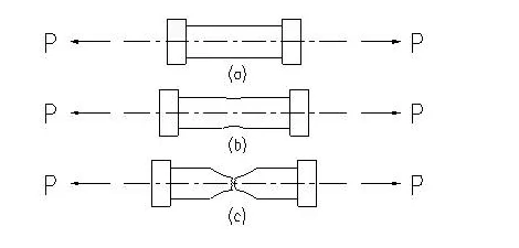
P -- tension force(N) ΔL -- Change in Length
The tensile testing machine will plot a curve (Figures -d ) which shows the force and the strain or movement that occurs during the test.
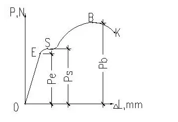
Figures-d
This test provides the elastic limit, elongation, yield point, yield strength, tensile strength, and the reduction in area.
“Quote:
When a sufficient load is applied to a metal, it will cause the material to change shape. This change in shape is called deformation. A temporary shape change that is self-reversing after the force is removed, so that the object returns to its original shape, is called elastic deformation. In other words, elastic deformation is a change in shape of a material at low stress that is recoverable after the stress is removed. When the stress is sufficient to permanently deform the metal, it is called plastic deformation.--CommunityCollege”
OE stage: The specimen will come back to its original dimension when the load is canceled and it will elongate in direct proportion to the tension force.This stage is elastic deformation stage.
The strain generated by metals from elastic deformation to plastic deformation is called the elastic limit(σe).
σe=Pe/Fo
σe -- Elastic limit(Mpa);
Pe -- the load on the metal enter plastic deformation(N);
Fo -- Original cross-sectional area of specimen(㎜2)
ES stage: The specimen would not go back to its original dimension even if the load was canceled and it will continue to elongate but without an increase in the force. This stage is the plastic deformation stage.
During the plastic deformation stage, the specimen has lost the ability of resistance to deformation, this phenomenon is called Yield. The minimum stress when yield phenomenon occurs is the yield point(σs) of the metal and it is the end of the elastic deformation.
σs=Ps/Fo
Note: σs — Yield Point(Mpa);
Ps -- load of deformation occurs to the specimen(N);
Fo -- Original cross-sectional area of specimen(㎜2)。
Deformation of the specimen will increases sharply with the increasing load after point B, which is the ultimate strength of the material. At point B, the specimen can no longer resist the load and will break at point K. And the maximum stress before the specimen break is call tensile strength(σb).
σb= Pb/Fo
σb -- tensile strength(Mpa)
Pb -- maximum stress before breaking(N)
Fo -- Original cross-sectional area of specimen(㎜2)
Yield Strength(σs), tensile strength(σb) and yielding-to-tensile ratio(σs/σb) are important mechanical properties to evaluate the quality of metals and are also the main bases for design and select materials.
1) Elongation(δ): Elongation is calculated by dividing the elongation at the moment of rupture by the initial gauge length and multiplying by 100
δ=ΔL/L0×100%
δ -- elongation(%);
ΔL -- Change in Length(mm)
L0 -- Initial Length(mm)
2) Reduction of Area(φ): Reduction of area is obtained from the tensile test by measuring the original cross-sectional area of the specimen and relating it to the cross-sectional area after failure.
φ= ΔF/F0 * 100
φ -- Reduction of area(%)
ΔF -- Change in area(㎜2)
F0 -- Initial Area(㎜2)
Ductility is positively correlated with elongation and reduction of area. Good ductility of metals is necessary in plastic working.
1) Brinell hardness:
The Brinell hardness is based on the load applied to the hardened ball in kilograms and press the ball into the surface of the specimen. After removal of the load, the resultant recovered round impression is measured across the indent at right angles using a low-power microscope or an automatic measuring device and the average value used to calculate hardness.
The actual Brinell hardness (HB) is calculated by factoring the indent size and the test force, such that:
HB = 2L / πD/2(D - √(D2 - d2))
L -- load,
D -- diameter of the ball indenter,
d -- diameter of the impression.
Brinell hardness testing is typically used in testing aluminum and copper alloys (at lower forces) and steel and cast irons at the higher force ranges.
2) Rockwell hardness
Rockwell method measures the permanent depth of indentation produced by a force/load on an indenter. First, a preliminary test force (commonly referred to as preload or minor load) is applied to a sample using a diamond or ball indenter. This preload breaks through the surface to reduce the effects of surface finish. After holding the preliminary test force for a specified dwell time, the baseline depth of indentation is measured. The hardness of the specimen is better when the depth is smaller.
Generally, hardness is not only a mechanical property to determine the quality of metals, but also one of the technical requirements for the design of mechanical parts.
Toughness is evaluated in terms of impact strength. A metal may possess satisfactory ductility under static loads but may fail under dynamic loads or impact. Toughness is most determined by the Charpy test.
Experiment shows that the toughness mainly depends on the strength of the metal. The higher the strength, the longer the service life of the metal.
The majority of engineering failures are caused by fatigue. Fatigue failure is defined as the tendency of a material to fracture by means of progressive brittle cracking under repeated alternating or cyclic stresses of an intensity considerably below the normal strength. Although the fracture is of a brittle type, it may take some time to propagate, depending on both the intensity and frequency of the stress cycles. Nevertheless, there is very little, if any, warning before failure if the crack is not noticed. The number of cycles required to cause fatigue failure at particular peak stress is generally quite large, but it decreases as the stress is increased. For some mild steels, cyclical stresses can be continued indefinitely provided the peak stress (sometimes called fatigue strength) is below the endurance limit value.
Fatigue strength design is one of the important strength calculations. Improving the structure shape to avoid concentration of stress and improving the surface roughness all can improve the fatigue resistance of the metal workpiece.
Technological properties are those qualities that give information regarding the suitability of metals for various technological operations or processes. Here we will discuss four of them: Castability, Malleability, Weldability, Machinability. These properties are very important in metal fabrication. And all these properties directly affect the technical processes, quality and cost of the equipment and components.
Factors that influence the castability of metals mainly include: fluidity, shrinkage, segregation and so on.
Fluidity -Fluidity is the flowability of molten metal. Metals of good fluidity are easy to fill the casting mold, and it’s easy to obtain quality castings;
Shrinkage - Shrinkage is a phenomenon that volume and size of the casting reduce during the process of resetting and cooling;
Segregation - segregation is the phenomenon that the produced permanent non-uniform distribution during the re-solidify and cooling process of castings. The segregation will cause a great difference in the mechanical properties of each part of the casting, which decreases the quality of the casting.
Most metals are of good castabilities, such as copper, iron, and so on.
Malleability is the comprehensive embodiment of plasticity and deformation resistance of metals. The better the plasticity, the smaller the deformation resistance, the better the malleability of the metal.
Brass and aluminum alloy have good malleability at room temperature, carbon steel has good malleability by heating; Cast iron, cast aluminum, bronze are hard to forge.
One of the main objectives of welding is to create a joint that is free of cracks and that can withstand the stresses placed on it. When nearly any welding process can be used on metal and minimal effort is required to produce a sound weld, the metal is said to have “good weldability”.
Weldability of metal is not an intrinsic property as it is influenced by, there are many factors that influence the weldability of metals. Below are some of the most important ones:
Metallurgy – The science of heating or manipulating metals to produce desired properties or shapes in them.
Welding Process – There are more than 67 welding processes. Various factors set them apart: how the heat and pressure are applied, how much heat and pressure are used, and the type of equipment employed.
Joint Design – The combination of the dimensions required for the welded joint and the geometry of the joint.
Weld Preparation – Weld preparation is a set of techniques to execute prior to welding to prevent defects in the weld. For example, one practice is to clean base metal before welding.
Melting Point – The temperature that must be reached for a solid substance to melt or fuse. When a metal has a medium melting point, it has better weldability.
Electrical Resistance – A metal’s opposition, or resistance, to the flow of electrical current. Metals with a high electrical resistance require more heat energy to weld and this makes them have poor weldability.
Generally, low carbon steel has good weldability. High carbon steel, high alloy steel, cast iron, and aluminum alloy have poor weldability.
Factors influence the machinability of metals mainly include:
- chemical components
- microstructure
- mechanical properties
- physical properties
- cutting conditions
- machine tools used
Generally, metals with proper hardness(170HBS - 230HBS) and enough frangibility are easy to be machined. It will improve the machinability of steel when changing its chemical components(add a small amount of plumbum, phosphorus,etc ) or heating. Copper has good machinability.
Metals are used widely in machinery and shipbuilding. It’s necessary to well know the properties of metals so that we can make right and full use of metals to improve the product's quality.
Source: Large Metal Fabrication Manufacturer -- Openex Mechanical Technology Col.,td
(Openex is a leading supplier of large metal machining and fabrication services including custom metal fabrication, structural steel fabrication, sheet metal fabrication, custom welding, steel process, cnc machining, etc. We have successfully completed thousands of custom projects in various industries: machinery, rail transit, power/energy, oil/gas, shipbuilding, bridge construction and so on.)
If you want to get more information about the properties of metals or you want to share your points with us, feel free to contact us at bell@openex.com.cn
The unexpected COVID-19 has caused a shortage of face masks. In order to alleviate the global face mask shortage amid the coronavirus pandemic, factories have been scrambling to make more surgical masks and KN95/N95 masks since February.
Generally speaking, KN95 masks and N95 masks have the same defending effect. The difference is that KN95 masks meet Chinese Standard, N95 masks meet NASI. CDC said that KN95 is on of the suitable alternatives to N95 masks and 3M has said that KN95 can be expected to function very similar to N95 masks. So wearing KN95 face mask or N95 face mask are all potential ways to prevent coronavirus. Now let’s learn more about the KN95 masks.
What are KN95 Masks?
Material analysis of KN95 masks
Executive standard of KN95 masks
How are KN95 masks are produced?
KN95 masks come from the GB2626-2006 “Respiratory protective equipment self-priming filter type anti-particulate respirator”, the ‘N’ stands for ‘Non-Oil, meaning that it offers protection against solid and non-oil-based particles; the ‘95’ refers to the filtration efficiency rating. KN95 masks should be filtering at least 95% of solid and non-oil-based particles.
KN95 masks used for defending various aerosol particles (including dust, smoke, droplets, etc.) suspended in the air, but KN95 masks can’t be used for medical purposes for KN95 masks without the function of fluid-resistant and defending liquid sprays and splashes.
Some KN95 masks feature exhalation valves, which help the wearer to breathe more easily. The filtering efficient of KN95s with exhalation valves is not that good. So wearing KN95s without exhalation valves is a better choice in the situation.
Here is the structure of KN95 Mask (Figure 1)

Figure1
Material of KN95 Mask
KN95 masks consist of 3-6 layers of nonwoven fabric (here we take the case of 4 layers).
1. The outermost layer is water blocking protective layer, it is harder than others.
2. The layer of melt-blown fabric is the core material, used for barrier and filtration, to ensure excellent filtration performance, we use the highest filtering level of this.
3. The layer of the hot air-through nonwoven fabric is fluffy, soft to the touch, keep warm, prevent moisture, and improve the comfort of wearing.
4. The innermost layer is a moisture-absorbing non-woven fabric, which absorbs the moisture from the mouth and nose and keeps the surface dry and comfortable.
KN95 masks also contain these materials: bendable nose clip(most made of aluminum or iron wire)and ear bands(which is secure for fixed mask)
Melt-blown fabric is the core material of a mask. Melt-blown is mainly made from polypropylene, its fiber diameter can be 0.5~1 μm. The melt-blown fabric has characteristics of complex structures, higher hardness, good connecting strength, and excellent oxidation resistance. And the application of melt-blown is very wide:
1, Health Care: surgical gown, protective clothing, disinfection package, mask, diaper, etc.
2, Home decoration: wall covering fabric, tablecloth, bedspread, etc.
3, Clothing: lining, fusible interlining, setting cotton, base cloth of various synthetic leathers, etc.
4, Industry: filter material, insulating material, cement sacks, Geocontainer, etc.
5, Agriculture: crop covers, etc.
6, others: space cotton, insulation material, deadening, sorbent mat, etc.
Melt-blown fabric is the bonded randomly scattered PP superfine fibers together. The randomly scattered PP super fibers have more thermal bonding opportunities, which make the melt-blown material have a larger superficial area and higher porosity (higher than75%). This means that the melt-blown fabric has good air filtration. Its unique structure determines it become good and irreplaceable materials of the mask.
The executive standard of KN95 masks is in line with international mainstream standards. GB2626 is almost the same as NIOSH, GB2626 in China is formulated based on the actual situation of China and reference to the US NIOSH standard. Here is a comparison of KN95, N95, and FFP2(Respectively executive standards are: GB2626-2006, NIOSH-42CFR84, EN 149-2001):
| Certification/Class (Standard) |
N95 (NIOSH-42CFR84) |
FFP2 (EN 149-2001) |
KN95 (GB2626-2006) |
| Filter performance-(must be ≥x% efficient) | ≥95% | ≥95% | ≥95% |
| Test agent | NaCl | NaCl and paraffin oil | NaCl |
| Flow rate | 85L/min | 95L/min | 85L/min |
| Total inward leakage | N/A | ≤8% leakage | ≤8% leakage |
| Inhalation resistance | ≤ 343 Pa | ≤ 70 Pa (at 30 L/min) ≤ 240 Pa (at 95 L/min) | ≤ 350 Pa |
| Flow rate | 85 L/min | Varied | 85 L/min |
| Exhalation resistance | ≤ 245 Pa | ≤ 300 Pa | ≤ 250 Pa |
| Force applied | -245 Pa | N/A | -1180 Pa |
| CO2 clearance requirement | N/A | ≤ 1% | ≤ 1% |
Mask Types Chart. Source:3M
Definitions:
Filter performance – the filter is evaluated to measure the reduction in concentrations of specific aerosols in the air that passes through the filter.
Test agent - the aerosol that is generated during the filter performance test.
Total inward leakage (TIL) – the amount of a specific aerosol that enters the tested respirator facepiece via both filter penetration and face seal leakage, while a wearer performs a series of exercises in a test chamber.
Inward leakage (IL)– the amount of a specific aerosol that enters the tested respirator facepiece, while a wearer performs normal breathing for 3 minutes in a test chamber. The test aerosol size (count median diameter) is about 0.5 micrometers.
From the chart, it not difficult to see their similarities:
1, Filter efficient: N95 = FFP2 = KN95;
2, Respiratory resistance of N95, FFP2 and KN95 are almost the same;
3, The test agent of KN95 is the same with N95, the test agent of FFP2 can be paraffin oil.
There are also differences:
1, To be certified as a KN95 mask, the mask must fit tests on real humans with ≤ 8% leakage. Which is the same with the FFP2 mask. The N95 mask standard does not require the test.
2, To be certified as a KN95 mask, ear bands of the mask must keep 10 seconds non-breaking under a tension force of 10N.
Other differences between N95 masks and KN95 masks are that KN95 masks mostly use the ear hook wearing method whereas the N95 masks use a two head-strap, one that goes around the back of the head under the ears and another that goes on the top over the crown of the head above the ears. This really comes down to personal preference in terms of which one is more comfortable for wearers as well as the level of safety and protection one feels is necessary given the particular activity being carried out.
After the breakout of the COVID, many large enterprises in China begin to shift to produce masks. And the mask productivity of China has increased to 200 million from 30 million in less than 30 days, which is impossible without mask making machine. Mask making machine produces various masks with certain filtering performance from multi-layer non-woven fabrics through the process of hot pressing, folding shaping, ultrasonic welding, scrap removal, ear-loop welding, nose clip welding and so on. Mask making machine is not a single machine, it requires the cooperation of multiple machines to complete a variety of different processes.
Here is the overall structure drawing of an automatic KN95 mask-making machine:

Main production steps of making KN95/N95 Masks:
1, Feeding: put non-woven fabric, hot air cotton, melt-blown fabric, and nose clip in the feeding area of automatic mask-making machine;
2, Sealing of nose wire;
3, Press-fit: press-fit the inner layer and outlay of the mask by hot pressing;
4, Welding of earloop: weld the ear loop onto the mask by the ultrasonic welder, and the welding points will not influence the filtering efficiency of masks. It needs about 5 seconds to complete the ear loop welding of one mask.
5, Slicing: cut off the edges of the mask by stamping
6, Fold forming.
A qualified KN95 mask needs to be implemented in accordance with GB2626, clearly indicating information about wearing methods and environment, and giving reasonable suggestions to the wearer.
A mask shouldn't only be able to protect you from all the pollutant particles, bacteria, and viruses, but it also needs to be well-made and well-fitting to enhance its protective efficiency.
(Openex has designed a high efficient KN95/N95 Face Mask Machine with a capacity of 300pcs/m, whose capacity is 3 times of the KN95 face mask production lines on the market. The first high efficient KN95/N95 mask production line has been shipped to the customer’s factory and put into use. )
If you want to get more information about the KN95 Masks or KN95/N95 Mask making machine or you want to share your points, feel free to contact us at bell@openex.com.cn
Steel structure (steel construction) is a kind of structure composed of steel materials, and it is one of the most popular building structures at present. The steel structure is mainly composed of steel bean, steel column, steel truss and other components made of section steel and steel plate. The components or parts are usually connected by welding, bolts, or rivets. The steel structure is widely used in large plants, long-span bridges, multi-story buildings and other fields for its light deadweight and easy construction.
Features of steel structure
Selection rules of steel structure
Application of steel structure
Connections of steel structure

| Advantages | Disadvantages |
| 1, Low self-weight and high strength to weight 2, Stiffness 3, Suitable for mass production 4, Quick installation 5, High ductility 6, No formwork required 7, Easy to transport 8, Easy to recycle 9, Allows off-site fabrication and on-site construction |
1, Susceptible to corrosion and requires frequent treatment with special paints 2, High upfront cost 3, Requires highly skilled labor 4, Higher maintenance cost 5, Low fire resistance 6, Susceptible to fatigue when exposed to constantly changing loads 7, Susceptible to brittle fracture when its ductility is lost |
The material selecting principle of steel structure is ensuring the carrying capacity of its bearing structure and preventing brittle failure under certain conditions. The material selection of steel structure is decided according to the importance of the structure, load characteristics, structure types, stress states, connection methods, the thickness of steel, and the working environment.
“Steel Structure Design Code (GBJ)” GB50017-2003 suggests four types of steel that are appropriate for steel structure. Those four types of steel are the first choice under permit conditions but not limited, you can also choose other steels as long as they meet the specs.
Commonly used designations of steel:
Ø Carbon structural steel: Q195, Q215, Q235(A36/S235), Q255, Q275, etc.
Ø Low-alloy high-strength structural steel
Ø Quality carbon structural steel and structural alloy steel
Ø Special steels
Using steel structure is selected not only according to its characteristics but also considered comprehensively according to the specific situation.
In addition to the characteristics of the industry, the application of steel structure must also be considered in combination with specific conditions. The applications of steel structure are as follows:
1, Workshop structure
Workshops with large lifting capacity cranes or with heavy work most use steel structures. For example, the open-hearth workshop, blooming workshop and mixer workshop of metallurgical plant and the steel casting workshop, hydraulic press workshop and forging workshop of heavy machinery plant and the berth workshop of the shipyard, the assembly workshop of the aircraft manufacturer, etc. The main load-bearing skeletons of these workshops are usually all or part of steel structures. Recently, more and more general industrial workshops use grid structures with the wide application of steel structures.
2 Long-span structure
It is used in the hall, gymnasium, exhibition hall, theatre, hangar, garage, bridges, etc. The main structural systems adopted are frame structure, arch structure, grid structure, suspension structure and prestressing steel structure.
3 Tower mast structure
Used for tower mast structures such as TV towers, microwave towers, high voltage transmission line towers, chemical exhaust towers, atmospheric monitoring towers, oil drilling towers, rocket launching towers and radio masts, etc.
4 High rise building
The framework of multi-story and high-rise buildings can adopt steel structures. As with multi-story and high-rise or super high-rise buildings in industrial buildings such as hotels, restaurants and so on, the frames should adopt frame structure systems, frame support systems, and frame shear wall systems.
5 Structures subjected to vibration loads or earthquakes
Just like workshops with large forging hammers, the skeleton structure bears extremely strong indirect vibrations although it doesn’t need bearing too much load. Steel structure should also be adopted for structures with high seismic resistance requirements
6, Shell structure
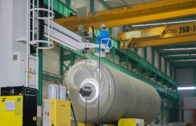
Containers made of steel plates are widely used in metallurgical, petroleum, and chemical enterprises, such as large liquid storage, gas storage, blast furnace, hot blast stove, etc.
7 other structures
Such as trestle, pipe support, derrick, offshore production platform, etc.
8 Removable structure
It is used for assembly movable houses, temporary exhibition halls, etc.
The steel structure has already been widely used. Steel structures are most popular especially in many industrialized countries like the USA, Japan, UK and Australia. Generally, steel structures can be prefabricated, which can simplify the process of the buildings. Openex is a professional company in large steel fabrication and steel machining. We have rich experience in prefabricating steel structures, which help us obtain consistent high praise from customers.
If you have anything to share with us or want to know more about prefabricated steel structure, don’t hesitate to contact us at bell@openex.com.cn
Resources:
https://www.egr.msu.edu/~harichan/classes/ce405/
The temperature in some factories and workshops gets higher and higher as hot summer comes.
We know that temperature change will greatly affect the working accuracy of the precision CNC machine, which will lead to problems of the precision equipment, such as working accuracy unstable or even equipment failure. Why and how can we avoid these problems?
1 Working accuracy unstable
The influence of temperature cannot be ignored for high-precision machining because the temperature difference is the killer of accuracy. Generally, practically all substances expand when heated and contract when cooled. The linear expansion of one-meter steel will be 12μm in length when the temperature changes 1 degree. This fact will not change with different locations or different equipment.
Most precision machines are made of steel, cast iron and other metal materials, whose length and shape vary with the changing temperature or the heat generated by the working equipment.
The expansion coefficient of steel is shown below:
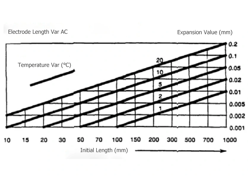
For example:
Piece length: 200mm
Temperature difference: 10℃
Expansion value:0.02mm
The expansion coefficient of copper is shown below:
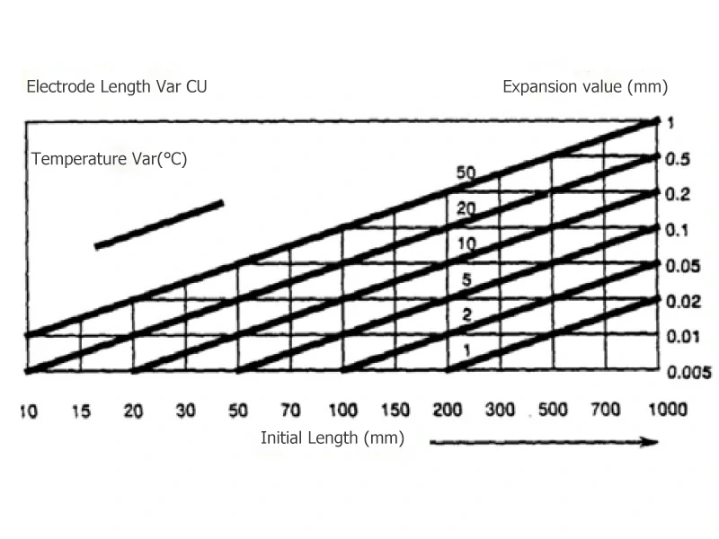
For example:
Piece length:200mm
Temperature difference: 10℃
Expansion value:0.05mm
Factories without precision machining experience often attribute the working accuracy unstable to the precision of the equipment. While factories with precision machining experience know clearly that even high-precision machine tools can only obtain stable working accuracy under a stable temperature environment and thermal equilibrium state. They attach great importance to the environmental temperature and the thermal balance of the machine tool.
For high-precision machining of accuracy less than 3μm, the ambient temperature must be controlled at a constant 20℃ with fluctuations less than 0.5℃/hour, and the air conditioning system maintains a constant temperature with a difference of ±1℃ throughout the day.
2, Equipment failure
In summer, the temperature of workshops without air conditioner will exceed 40℃, some good CNC machine tools will inevitably breakdown. How to avoid the breakdown of CNC machine tools at high temperatures?
1)Prevent the CNC machine tools from damaging by condensate water
Many machine tools use operating fluid including machining center, slow-feeding wire cut machine, and so on. When the ambient temperature is too high, the temperature of the operating fluid will be higher. Although those machine tools are usually equipped with a refrigerator, the machine tool will shut down once the temperature of the operating fluid is too high. The purpose of a refrigerator is to ensure that the working fluid is at the same temperature as the ambient temperature by adjusting the temperature of operating fluid because the temperature of the operating fluid will rise higher than the ambient temperature during the runtime of the machine tools. On summer days, the ambient temperature may be as high as 40℃, although the machine tools can normally work for the moment if the temperature of operating fluid is set much lower than the ambient temperature for example 20℃. However, high ambient temperature and low operating fluid temperature will lead to a large amount of condensed water around the operating fluid tank of the machine. It will inevitably lead to serious rust of the parts with condensed water as time goes on. There is condensed water even at the circuit board of some machine tools, which will bring serious results.
So, the right use of a refrigerator is to set the temperature of operating fluid to the same as the ambient temperature. Here, there is an important precondition: suitable ambient temperature. Installing air-conditioner system to ensure a suitable ambient temperature is a basic requirement especially for precision CNC machines.
2) Prevent temperature rise of CNC equipment
For ordinary CNC equipment, many factories do have no air-conditioner system to ensure an isoperibol. Some measures must be taken to ensure the normal running of CNC equipment.
(1) Ensure the air conditioner of distribution box functioning well
(2) Keep the door of distribution box closed
(3) Ensure the cooling fan of motor and circuit board function well
(4) Periodic clean the cooling ducts and radiating fin of the high-power circuit board
(5) CNC equipment should be inspected regularly to remove hidden risks
In short, the temperature control environment is very important for precision CNC equipment on hot summer days.
As a professional CNC Machining service supplier, Openex is familiar with various features of metal materials such as the heat-expansion and cold-contraction. Workpieces with high accuracy requirements that need to be machined at a temperature control workshop will not be machined at a non-temperature-control workshop. On the contrary, workpieces with low accuracy requirements don't need to be machined at a temperature control workshop. Specifically, it is determined according to the customer's accuracy requirements, workpiece dimension, and ambient temperature. We, Openex, exactly know this!
Flow drill technology (the process is also known as flow punch forming, friction drilling, thermal friction drilling) is a method of making holes chip-less in thin-walled metal components or tubular components in which the material is pushed out of the way with the aid of heat from friction. The flow drill is mainly made of cemented carbide with good wear resistance and high-temperature resistance. Flow drill has been greatly changed the traditional connection methods of thin-walled components and tubular components.

Background of flow drill developing
Working principle of flow drill – the process
In many areas of mechanical and plant engineering, aviation, and the construction industry, before the flow drill technology used, designers and production engineers were confronted with the challenge of connecting components and structural components. If fixed, non-detachable connections are required, depending on the area of application, the different non-detachable joining technologies are used. In particular, the processes of welding, soldering, or gluing are used to achieve a resilient connection. However, what possibilities are there if a detachable connection is required, e.g. so that components or assemblies can be assembled or dismantled on-site without great effort? In most cases, conventional bolted connections with bolts (external thread) and nuts (internal thread) are used. With this proven method, the desired elements can be connected and, depending on the requirements, disconnected again. However, the use of conventional screw connections reaches its limits when thin-walled components or hollow sections, in particular, are to be combined. For thin-walled components such as sheet metal constructions, the use of screw-nut connections is possible, provide that both sides are easily accessible for assembly. Depending on the requirements, different variants of “screw-nut” versions can be found here. Conventional screws and nuts are often used. However, the mentioned traditional joining methods are material-, time- and cost-intensive. The load-bearing capacity of the detachable connection is sometimes very limited and unintentional loosening of the weld nut, press-fit nut or rivet nut cannot be avoided. For thin-walled components and in particular, for hollow profiles, the flow drill technology is an economical alternative for producing a sheet metal pull-through and subsequent thread forming!
In the flow drill technology, a fast-rotating (1500-3000r/min) carbide taper mandrel is pressed onto the thin-walled component or sheet metal under axial force or with a feed movement. As the feed motion increases and the friction between the rapidly rotating tool and the stationary workpiece increase, the workpiece heats up very quickly in the contact zone. The further axial infeed of the tapered mandrel results in a rising friction surface and the workpiece heated up very strongly. Depending on the material and the resulting heat conduction, the temperature is up to approximately 650℃-750℃. This greatly reduces the yield stress of the workpiece and the process movers from the initial cold forming stage to the hot forming stage. The yield stress of the workpiece in the contact area is so greatly reduced that the flow drill can be pressed into the workpiece with considerably less force. The yield stress in the hot forming area is only about 10-20% of the yield stress at room temperature. As a further axial infeed of the tool continues, the original molten solid material in the hole flows thermo-plastically in the radial and axial directions, the bush forms on the underside of the workpiece. This bushing comes without any additional material or inserts, which offers enough space for machining the screw threads. The threads are forced into the workpiece by a non-cutting method. It is cold worked and compacted as forging without destroying the natural grain (fiber-running) of the material. Formed threads are characterized by extremely high strength and smoothness.
1, During the process, bushing forms on the underside of the workpiece, and the total thickness is 3 times the initial thickness. All this improve the thread precision, tensile strength, thread torque value, and stability;
2, Because of the strong friction between flow drill and the workpiece, the workpiece heats up sharply and then cool down in the air, which improves the hardness, rust-proof and corrosion resistance of the hole;
3, High processing speed, short cycle time. It just cost 2-6 seconds to obtain a hole, which improves working efficiency;
4, No need to deal with waste because of no chip, which simplifies the process and improve the utilization rate of the material;
5, The flow drill is easy to maintain for its simple structure, with long service life;
6, Flow drill can be used at standard drilling machines as well as CNC drilling machines. The bit holder of flow drill adopts sleeve chuck and the tool holder adopts Morse taper shank or Straight cylindrical handle, no need to add any hardware;
7, Flow drill can optimize, simplify, and improve the structure design and process route of the product, which is conducive to the subsequent assemble.
Flow drill is widely used in various industries including machinery, auto, aerospace, domestic appliance, metal furniture, lighting, and so on. Flow drill can machine various standard screw threads, metric threads, and NPT threads.
At present, the flow drill has been applied effectively. here are the parameters:
| Screw Dimension | Flow Drill Diameter(mm) | Rotate Speed(r/min) | Power(kw) | Time(s) |
| M2 | φ1.8 | 3200 | 0.5 | 2 |
| M3 | φ2.7 | 3000 | 0.6 | 2 |
| M4 | φ3.7 | 2600 | 0.7 | 2 |
| M5 | φ4.5 | 2500 | 0.8 | 2 |
| M6 | φ5.3 | 2400 | 1.0 | 2 |
| M8 | φ7.3 | 2200 | 1.3 | 2 |
| M10 | φ9.2 | 2000 | 1.5 | 3 |
| M12 | φ10.9 | 1800 | 1.7 | 3 |
| M16 | φ14.8 | 1400 | 2.2 | 4 |
| M20 | φ18.7 | 1200 | 2.7 | 5 |

As a professional heavy machining service supplier, Openex, aiming at optimizing the process, improve the products, reduce the cost, and improve efficiency, provides thin-walled components flow drill connection solution for customers. If you’re interested in the flow drill or other metal machining technology, feel free to contact us at Bell@openex.com.cn.
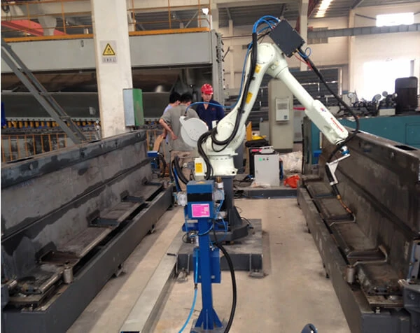
Along with the advancement of technology, improvement of living standards, and the development of the mechanical industry, traditional welding technology cannot catch up with the requirement of the fast-developing society. The more widely used automatic welding technology improves production, reduces costs, and increases working efficiency. Here we’ll further discuss the developing trend of automatic welding by deep learning the advantages and the principle of automatic welding.
Keywords: automatic welding, application, robotic welding
With the development of modern technology and digital electronic system, automation is getting closer and closer to our lives. The progress of automatic welding technology endows the welding industry with new vitality. The popularization of welding automation is of great significance to increase production efficiency, conserve energy, and reduce emissions. Therefore, researching the reasonable and efficient application of automatic welding technology in machining have much more significance.
Automatic welding is a complete mechanized and automated process of the whole welding process. Traditional welding refers to manual welding.
‘In manual metal arc welding, the arc is struck between a consumable electrode and the workpiece being welded. The electrode rod is melted at the tip of the arc and metal droplets fall into the weld pool. Thus, as welding progresses the welding electrode becomes shorter. The welder must maintain a constant arc length between the workpiece and the tip of the electrode as the electrode moves along the joint seam while compensating for the burn-off rate of the electrode.’ --Sciencedirect
Automatic welding is different. The welding process is completed mechanized by modern electronic and digital technology. Automatic welding includes semiautomatic and fully automatic. In semiautomatic welding, an operator manually loads the parts into the welding fixture. A welder controller then keeps the welding process, the motion of the torch, and stillness of the parts to preset parameters. After the weld is completed, the operator removes the completed assembly and the process begins again. In fully automatic welding, it doesn’t require a manual welder to perform them, but instead, an operator controls the machine or robot which carries out the welds. A custom machine, or series of machines, loads the workpiece, indexes the part or torch into position, accomplishes the weld, monitors the quality of the joint and unloads the finished product.
Here are the most basic components of an automated welding system, all of which are important to the automated welding process:
Wire Feeder: This moves filler wire into the robot at a programmed rate. This filler wire is often used to add material to a weld to support the joint.
Welding Robot: This includes the robot and the tool at the end of the arm, typically a torch or other manipulator. These robots come in two types: articulating robots and rectilinear robots. Rectilinear robots can move their primary arm in three directions and rotate a wrist at the end of the arm. Articulating robots have rotating joints — these allow for more freedom of movement and range of motion outside of three dimensions.
Wire Cleaner: The cleaner is used to remove spatter from the torch between work cycles, prolonging equipment life span.
Torch: The torch uses power flowing to an electrode to heat up and join metals together. Arc welding units also have an arc shielding apparatus included in the torch. Also, an air- or water-cooling unit is usually included.
Work Area: This is where parts are placed and held for the robot to weld. Fixtures hold the parts in place as the robot completes its welds.
Controller: This component is effectively the “brain” of the welding cell, supplying power and instructions to the robot using stored programs.
Teach Pendant: This handheld interface system allows the operator to set welding parameters, manually move the robot and input new programs.
Welding Power Supply: This supplies power to the welding torch. This will vary in size and performance depending on the requirements of the parts being welded. The power supply differs slightly depending on whether the cell is an arc welding unit or a spot-welding unit.
Stack Light: This light indicates what the cell is doing at any given time. Generally, a red light indicates an emergency stop, an orange light means the robot is being programmed and green means the cell is running automatically.
Operation Box: This box contains controls to start and stop a cell, and it contains buttons for each function, including a restart button to reset the cell after a malfunction has been resolved.
Safety Features: Most robotic welding machines will include safety features to prevent harm to workers and operators. These include fencing, arc shielding, access doors, and other features to reduce worker exposure to hazardous light, fumes and motion as a cell works.
Automated welding systems offer four main advantages: increased productivity, improved weld quality, decreased scrap, decreased variable labor costs, and improved operating environment more easily.
1, improved productivity A mechanized welding system can easily outpace a skilled manual welder. The production weld speeds of automated welding are set at a max percentage by the machine, not by an operator. Automated welding systems can run 24/7 without a break. Automated welding is faster than doing it manually and certainly more consistent, which simplifies production planning and management because a stable cycle time leads to predictable output per hour, shift and day.
2, improved quality Automated welding systems ensure weld integrity through electronic weld process controllers. Combining mechanized torch and part motions with the electronic recall of welding parameters result in a higher quality weld than can be accomplished manually. Consistent motion also means consistent quality. With the torch and workpiece(s) in the same position and moving at the same speed every time, each part is welded the same way. There's no risk of variation, and as the robot never tires, the last piece produced is identical to the first. Especially for safety-critical parts, automation gives customers confidence in the integrity of each weld.
3, save costs Shorter cycle times and longer working hours add up to a lower cost per weld, but that's not the only cost savings. Automated welding cuts both scrap and consumable costs.
Decreased scrap: Human error is always possible, even with the most skilled welders. However, every movement a welding robot makes is planned and automated, reducing mistakes and, therefore, reducing the number of scrapped parts.
Decrease wastes: Consumables are yet another source of waste. Consumables include nozzles and other components with relatively short life spans that are replaced after a certain number of uses. Robotic welding units increase welding speed and minimize excess energy use, increasing the lifespan of each consumable component. This means new consumables are purchased less frequently, saving costs.
4, save energy Automated welding systems conserve energy by running consistently, cutting the energy-expensive start-ups. Additionally, robots do not over weld and reduce the need for corrective welding, cutting energy expenditure.
5, safer working conditions Welders need protection against the arc flash and the weld’s heat. Automated welding keeps workers away from these hazards and creates a safer, more pleasant working environment. Plus, there’s no need to invest in additional personal protective equipment.
When using Automatic welding is most commonly used in the manufacturing and engineering industries to increase efficiency. The typical models of automatic welding technology used in mechanical welding are mechanical arms and welding robots. Programs are input via the teach pendant and saved to the controller, which tells the robot what to do. These programs move the welding robot and manipulate the torch on the end of its arm, placing it exactly where it needs to be at any point. The torch heats up, using a power supply to generate enough heat in the metal to fuse parts permanently. The wire feeder feeds extra material to the robot arm to do this. Between parts, the arm moves the torch to the wire cleaner to remove any spatter.
Instead of choosing a robotic welding setup manufacture, you can choose a contract manufacturer with welding robots for OEM. As a professional metal fabrication manufacturer, Openex possesses various welding machines and has skilled welders certified by AWS, CSS, RINA, LR, DNB, API as well as ASME. We are experienced in the following welding process: Arc Welding, MIG Welding, TIG Welding, Shielded Metal Arc Welding, MAG Welding, Plasma Arc Welding, and so on. Custom welding services from the professional welders at Openex are sure you get the results you are looking for in product manufacturing and custom fabrication.
If you need complete custom fabrication or just simple welding fabrication services, contact us right the time.
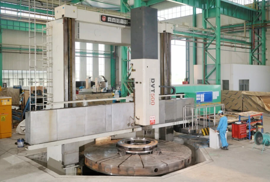
In the application of CNC technology in large fabrication, it's necessary to transfer the pre-prepared operation program to the electronic computer, then the machine tools can be totally operated and controlled through the computer, which greatly increases the work efficiency, quality, and precision of the large fabrication project.
CNC machine tools are a typical product of mechatronics. CNC machine tool control technology is a multi-disciplinary comprehensive technology integrating computer and software technology, automatic control technology, electronic technology, automatic detection technology, hydraulic and pneumatic technology, and precision machinery.
CNC machine tool is not free from disadvantages: high initial cost. However, the benefits far outweigh the disadvantages when you're working with that dependable CNC technology. There can be many benefits of using CNC machine tools for metal fabrication projects, including (but not limited to):
CNC machine tools are highly adaptable to different parts, and can machine parts with complex shapes. Just by changing the program, the CNC machine tool can adapt to the automatic machining of different types and sizes of workpieces. This provides great convenience for single-piece, small-batch production and trial production of new products with complex structures. Especially for workpieces with precision complex surfaces (such as spiral surfaces) which are difficult or impossible to machine by ordinary machine tools, CNC machine tools can realize the auto machining as well.
At present, the minimum movement (pulse equivalent) of tools and worktables controlled by CNC machine tools is generally 0.0001mm. And the CNC system can automatically compensate for the backlash and screw pitch deviation of the feed drive chain so that the CNC machine tool can achieve high precision.
Furthermore, the auto machining method of CNC machine tool avoids the deviation caused by the man-made operation. Therefore, the same batch of workpieces has a better size consistency, high pass rate and stable machining quality.
Due to the high rigidity of the CNC machine tool structure, it allows powerful cutting with a large amount of cutting. The speed and feeds of the auxiliary shaft and spindle are larger than that of ordinary machine tools. Therefore, the selectivity of the optimal cutting amount improves the cutting efficiency of the CNC machine tool and saves time. The production efficiency of CNC machine tools can be 2-3 times higher than that of ordinary ones.
By using CNC machine tools can save time for marking, adjustment, machining, and inspection, and can save production costs, tooling design, and manufacturing costs.
CNC machine tools have high-level automation, that can greatly reduce the labor intensity of workers so which reduces the number of operators. Meantime, it is conducive to modern management and can be developed into a more advanced manufacturing system.
It’s vital to do an inquiry before choosing a metal fabrication service supplier, as not all suppliers are capable of completing the same quality of work. Openex has world-class CNC machine tools to provide top machining services. As a full-service metal fabricator, Openex has many years of experience and is skilled in all types of metal fabrication services and would be honored to use top CNC machine tools to highly implement your designed workpieces, saving you time and money with fewer headaches.
General description
Dual-phase stainless steel, commonly known as Duplex stainless steel (DP steel or DSS),is a low-Nickle (4.5-6.5) stainless steel, because of its metallurgical structure containing two phases, ferrite (body centered cubic lattice) and austenite(face-centered cubic lattice) each with about 50% percentage respectively, it takes good characteristic from both austenitic and ferritic, ie. has good mechanical properties, corrosion resistance, and also weldability.
Historical development and its advantage
The DSS was first produced in the USA in the 1940s and is in its 3rd generation as of 2020 now. the biggest advantage of DSS is high yield strength up to 400-550Mpa, almost double of usual single-phase stainless steel. Hence, it can save the usage of steel, therefore reducing general costs.
The 2nd biggest advantage is its good performance in anti-corrosion, especially in the bad circumstance such as seawater, Chloridion rich area, compared to usual austenite stainless steel, DSS has much better resistance in pitting corrosion, crevice corrosion, and stress corrosion, and it also its fatigue of corrosion is very low, that only high alloy austenite stainless steel can compete with it.
Other advantages of DSS are:
l High ultimate tensile strength(UTS, enabled by the martensite), with low initial yield stress (provided by the ferrite phase)
l Low yield to tensile strength ratio (yield strength / tensile strength = 0.5) which is good to prevent sudden failure of metal components.
l High initial strain hardening rates
l Good uniform elongation
l A high strain rate sensitivity(the faster it is crushed the more energy it absorbs)
Disadvantages of DSS:
Compared to austenite stainless steel(ASS)
1 DSS is not as universally suitable as ASS, eg, can not be used under 250℃
2 Plasticity and toughness are lower than austenite ASS, therefore its cold-forming and hot-forming performance is somehow inferior
3 There exists a mid-temperature brittleness area, which need to be careful to generate harmful phase during heat treatment or welding procedure
Nevertheless, thanks to its excellent advantages described before, DSS has become more and more popular to be used in heat exchangers and pipes for the industries of oil, natural gas, paper making, fertilizer, marine engineering, and chemical, and has also become widely used to make structural components in the industries of the bridge, airplane, ship, automotive, etc.
Nowadays, there are mainly four types of dual-phase stainless steel (DSS) classified by alloy content, each country has a different grade, below listed are that of six countries:
| Duplex stainless steel(DSS) is classified by alloy content | ||||||
| Type name | China | USA | Sweden | Germany | France | Japan |
| Low Alloy DSS | 00Cr23Ni4N | UNS-S32304 | SS2327 (SAF2304) |
W.Nr.1.4362 | UR35N | DP11 |
| Mid Alloy DSS | 00Cr18Ni5Mo3Si2 00Cr22Ni5Mo3N |
UNS-S31500 UNS-S31803 |
SS2376(3RE60) SS2377(SAF2205) |
W.Nr.1.4417 W.Nr.1.4462 |
UR45N | DP1 DPS |
| High Alloy DSS | 00Cr25Ni5Mo2 00Cr25Ni7Mo3WCuN |
UNS-S32900 UNS-S31260 |
SS2324(10RE51) | W.Nr.1.4460 W.Nr.1.4501 |
329J1 329J2L |
|
| Super DSS | 00Cr25Ni7Mo4N 00Cr25Ni6Mo3CaN |
UNS-S32750 UNS-S32550 |
SS232(SAF2507) | W.Nr.1.4410 W.Nr.1.4507 |
UR47N+ UR52N+ |
|
We just finished a custom machining job-- end rings for an environment protection machine that is used in chloride circumstances.
The rings are made of Duplex stainless steel SAF 2205 with a thickness of 16mm.
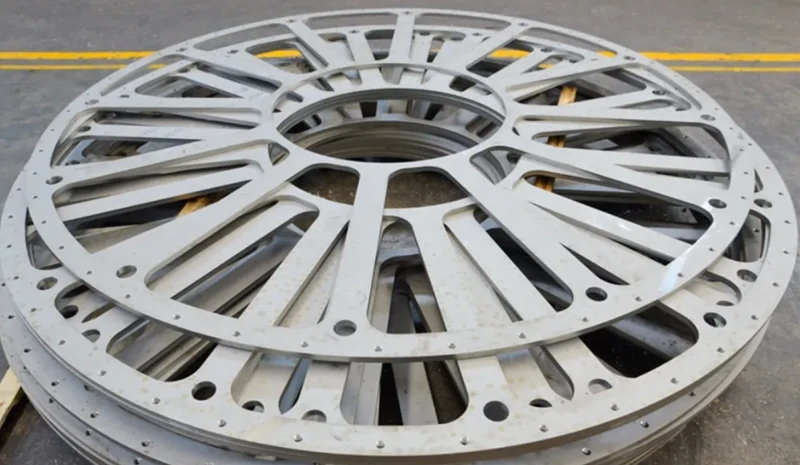
Here below is the chemical composition for SAF2205:
C≤0.030 Mn≤2.00 Si≤1.00 p≤0.030 S≤0.020 Cr 22.0~23.0 Ni 4.5~6.5 Mo3.0~3.5 N0.14~0.20
Compared with single-phase stainless steel 304 and 316L, DSS SAF2205 has better performance, especially on anti-chloride corrosion.
| Comparison between dule phases stainless steel SAF2205 and single phase stainless steel 304 and 316L | ||||
| SAF2205 | 304 | 316L | Remark | |
| Anti-chloride corrosion | >1000 | 47 | 152 | Time got corrosion and breakage(h) 40%Cacl2, 100℃ |
| PREN | 35.4 | 18.4 | 25.9 | Pitting resistance equivalent numbers, the larger the better |
| Anti-inter-crystalline corrosion | The best | Normal | Better | |
| Anti-uniform corrosion g.(m2.h)-1 |
0.021 | 57 | 12.1 | 20%H2SO4 60℃ 100h |
| Anti-fatigue | The best | Normal | Better | |
| Tensile strength Rm((Mpa)≥ |
620 | 485 | 485 | Rm((Mpa)≥ 1020-1100℃ water quenching |
| Yield strength Rp0.2(Mpa)≥ |
450 | 170 | 170 | Rm((Mpa)≥ 1020-1100℃ water quenching |
| Elongation A50(%)≥ |
25 | 40 | 40 | Rm((Mpa)≥ 1020-1100℃ water quenching |
| Hardness (Brinell/Rockwell)≤ |
290/30.5 | 187/90 | 187/90 | Rm((Mpa)≥ 1020-1100℃ water quenching |
| Thermal conductivity w/(m. ℃) |
19 | 18 | 15 | 20-100℃ |
| Liner thermal expansion (10-5/℃) |
13.7 | 16 | 16 | 20-100℃ |
| Weldability | Excellent No need for pre-heating, or post-heating |
Good, but can not have pre-heating or post-heating to rectify deformation | Might get crackle in high temperature | |
| General performance | The best | Normal | Better | |
It is reported that a Seamless pipe made of SAF 2205 has been used for an 850km long pipeline to pump the LNG across China from the western to the eastern, thanks to its excellent mechanical properties and weldability.
In the last few years, we’ve offered steel fabrication services for about 40 duplex stainless steel chemical cargo ships. The total weight of processed stainless steel was up to 38000 tons. By the end of June this year, we have completed the stainless-steel fabrication services of 8, total 3300DWT, chemical cargo ships for Jiangsu New Times Shipbuilding Co. At present, we still have the large fabrication projects for more than 10 large tonnage chemical cargo ships to process from other shipbuilding companies, and orders have already been scheduled to the second half of next year.
According to the statistics from China Shipbuilding Industry Association, the national shipbuilding completion in the year 2020 is about 35.3 million DWT, and the new ship orders undertaking is 21.1 million DWT.
The shipbuilding industry has a great demand for stainless steel. Thanks to the continuous breakthroughs made in the research and development and the application of duplex stainless steel, many domestic shipyards have successfully completed the localization of stainless-steel chemical tankers. According to the relevant statistics, there will be a total of 283 refined oil, chemical cargo ships with 6.3 million DWT by the end of the year, among which the DWT of chemical tankers need duplex stainless steel is about 2 million. It’s estimated that about 120 thousand tons of duplex stainless steel will be needed.
In recent years, Chinese iron & steel enterprises have rapidly developed especially in the R&D of duplex stainless steel. Breakthroughs have been made at AOD furnace smelting nitrogen precise control, thermoplastic control, heat treatment, efficient pickling, welding, and composite material manufacturing, they have already developed a series of duplex stainless steels whose quality and performance are increasingly improved. It supports a lot in shipbuilding.
We take fabrication, sale, and technical service as a modern comprehensive steel service with metal fabrication centers, modern inspection centers, and 9 processing centers include cutting, slitting, grinding, forming, welding, heat treatment, machining, assembling, painting.
The chemical cargo ship plate made from duplex stainless steel which has a very high technical requirement at welding, corrosion resistance, scratch preventing, grinding, pickling, and passivating. Especially the design of the corrugated bulkhead, not only needs to ensure stability but also to enhance the strength, rigidity, and corrosion resistance. And the number of every ship's parts can be up to several thousand, the huge amount of product categories is a severe test of material control, production site management, planning control. That why it’s difficult to fabricate the chemical cargo ship plate.
Over the years, we’ve introduced advanced processing equipment from abroad, and now have large, medium, small machining centers, boring and milling machines, deep drilling machines, 5 Axis machining centers, multi-hole drilling machines, etc. We have the welding capacity of large steel structures, duplex stainless steel ship plate, pressure vessels, cylinders, and so on. Our welding processes including NGW (Narrow gap welding), BESW (strip surfacing), automatic arc welding, GMAW, rod arc welding, plasma welding, etc. And we are ISO, CE, ASME, API, LR, AWS certified.