Humans have used windmills to capture the force of the wind as mechanical energy for more than 1,300 years. Unlike early windmills, however, modern wind turbines use generators and other components to convert energy from the spinning blades into a smooth flow of AC electricity.
Today we’ll be looking at the definition, history, working principle, manufacturing process, types, as well as futures of wind turbines.
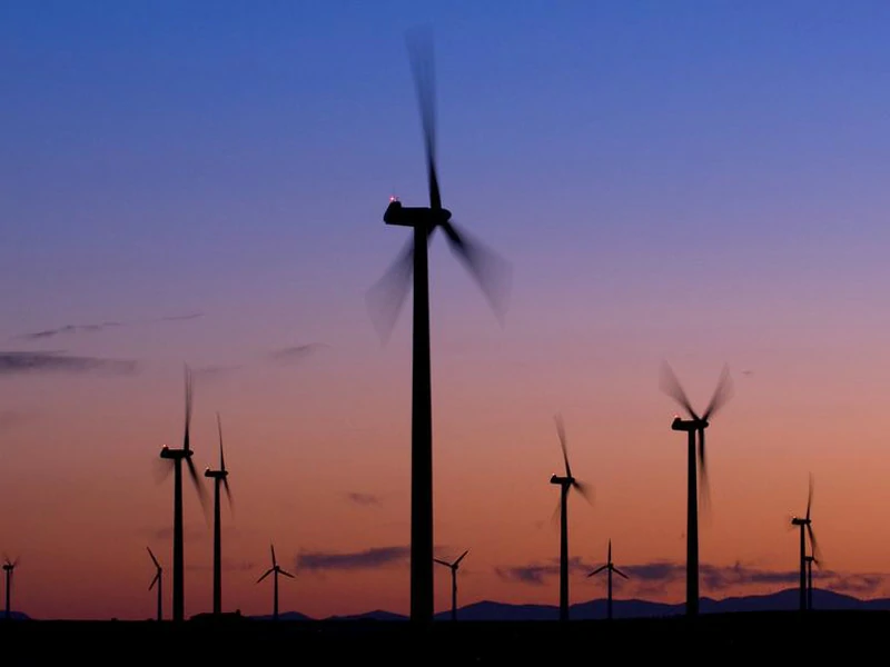
A wind turbine is a machine that converts the wind's kinetic energy into rotary mechanical energy, which is then used to do work. In more advanced models, the rotational energy is converted into electricity, the most versatile form of energy, by using a generator.
Wind power has been used as long as humans have put sails into the wind. King Hammurabi's Codex already mentioned windmills for generating mechanical energy. Wind-powered machines used to grind grain and pump water, the windmill and wind pump, were developed in what is now Iran, Afghanistan, and Pakistan by the 9th century. Wind power was widely available and not confined to the banks of fast-flowing streams, or later, requiring sources of fuel. Wind-powered pumps drained the polders of the Netherlands, and in arid regions such as the American mid-west or the Australian outback, wind pumps provided water for livestock and steam engines.
The first windmill used for the production of electric power was built in Scotland in July 1887 by Prof James Blyth of Anderson's College, Glasgow (the precursor of Strathclyde University).Blyth's 10 metres (33 ft) high cloth-sailed wind turbine was installed in the garden of his holiday cottage at Marykirk in Kincardineshire and was used to charge accumulators developed by the Frenchman Camille Alphonse Faure, to power the lighting in the cottage, thus making it the first house in the world to have its electric power supplied by wind power. Blyth offered the surplus electric power to the people of Marykirk for lighting the main street, however, they turned down the offer as they thought electric power was "the work of the devil." Although he later built a wind turbine to supply emergency power to the local Lunatic Asylum, Infirmary, and Dispensary of Montrose, the invention never really caught on as the technology was not considered to be economically viable.
Across the Atlantic, in Cleveland, Ohio, a larger and heavily engineered machine was designed and constructed in the winter of 1887–1888 by Charles F. Brush. This was built by his engineering company at his home and operated from 1886 until 1900. The Brush wind turbine had a rotor 17 metres (56 ft) in diameter and was mounted on an 18 metres (59 ft) tower. Although large by today's standards, the machine was only rated at 12 kW. The connected dynamo was used either to charge a bank of batteries or to operate up to 100 incandescent light bulbs, three arc lamps, and various motors in Brush's laboratory.
With the development of electric power, wind power found new applications in lighting buildings remote from centrally generated power. Throughout the 20th century parallel paths developed small wind stations suitable for farms or residences. The 1973 oil crisis triggered the investigation in Denmark and the United States that led to larger utility-scale wind generators that could be connected to electric power grids for remote use of power. By 2008, the U.S. installed capacity had reached 25.4 gigawatts, and by 2012 the installed capacity was 60 gigawatts. Today, wind-powered generators operate in every size range between tiny stations for battery charging at isolated residences, up to gigawatt-sized offshore wind farms that provide electric power to national electrical networks.
Wind turbines produce electricity from wind. Sensors at the top of the turbine measure wind speed and direction to signal to the motor which way to point the nose (so it points towards the wind). The kinetic energy of the wind causes the blades to rotate, which spin a shaft connected to a generator that coverts the kinetic energy to electricity.
Raw Materials
A wind turbine consists of three basic parts: the tower, the nacelle, and the rotor blades. The tower is either a steel lattice tower similar to electrical towers or a steel tubular tower with an inside ladder to the nacelle.
Most towers do not have guys, which are cables used for support, and most are made of steel that has been coated with a zinc alloy for protection, though some are painted instead. The tower of a typical American-made turbine is approximately 80 feet tall and weighs about 19,000 pounds.
The nacelle is a strong, hollow shell that contains the inner workings of the wind turbine. Usually made of fiberglass, the nacelle contains the main drive shaft and the gearbox. It also contains the blade pitch control, a hydraulic system that controls the angle of the blades, and the yaw drive, which controls the position of the turbine relative to the wind. The generator and electronic controls are standard equipment whose main components are steel and copper. A typical nacelle for a current turbine weighs approximately 22,000 pounds.
The most diverse use of materials and the most experimentation with new materials occur with the blades. Although the most dominant material used for the blades in commercial wind turbines is fiberglass with a hollow core, other materials in use include lightweight woods and aluminum. Wooden blades are solid, but most blades consist of a skin surrounding a core that is either hollow or filled with a lightweight substance such as plastic foam or honeycomb, or balsa wood. A typical fiberglass blade is about 15 meters in length and weighs approximately 2,500 pounds.
Wind turbines also include a utility box, which converts the wind energy into electricity and which is located at the base of the tower. Various cables connect the utility box to the nacelle, while others connect the whole turbine to nearby turbines and to a transformer.
Before consideration can be given to the construction of individual wind turbines, manufacturers must determine a proper area for the siting of wind farms. Winds must be consistent, and their speed must be regularly over 15.5 miles per hour (25 kilometers per hour). If the winds are stronger during certain seasons, it is preferred that they be greatest during periods of maximum electricity use. In California's Altamont Pass, for instance, site of the world's largest wind farm, wind speed peaks in the summer when demand is high. In some areas of New England where wind farms are being considered, winds are strongest in the winter, when the need for heating increases the consumption of electrical power. Wind farms work best in open areas of slightly rolling land surrounded by mountains. These areas are preferred because the wind turbines can be placed on ridges and remain unobstructed by trees and buildings, and the mountains concentrate the airflow, creating a natural wind tunnel of stronger, faster winds. Wind farms must also be placed near utility lines to facilitate the transfer of electricity to the local power plant.
Modern wind turbines fall into two main categories:
Horizontal Axis Wind Turbines (HAWT)
Horizontal-axis wind turbines are those most common in the UK. They have three blades and operate "upwind," with the turbine pivoting at the top of the tower so the blades face into the wind.
Vertical Axis Wind Turbines (VAWT)
There are several types of vertical-axis wind turbines (VAWT), including the Darrieus model, where the blades revolve around a vertical shaft.
VAWTs have some advantages. They have fewer components, can be grouped closer together as they can operate in turbulent winds and can catch the wind in any direction - as opposed to HAWT which needs to be pointed into the wind.
However, VAWT’s tend to be less reliable and less efficient so not as well suited to large scale energy production.
The future can only get better for wind turbines. The potential for wind energy is largely untapped.
Extreme winds challenge turbine designers. Engineers have to create systems that will start generating energy at relatively low wind speeds and also can survive extremely strong winds. A strong gale contains 1,000 times more power than a light breeze, and engineers don't yet know how to design electrical generators or turbine blades that can efficiently capture such a broad range of input wind power. To be safe, turbines may be overbuilt to withstand winds they will not experience at many sites, driving up costs and material use. One potential solution is the use of long-term weather forecasting and AI to better predict the wind resources at individual locations and inform designs for turbines that suit those sites.
Climate change will bring more incidents of unusual weather, including potential changes in wind patterns. Wind farms may help mitigate some of the harmful effects of climate change. For example, turbines in cold regions are routinely winterized to keep working in icy weather when other systems may fail, and studies have demonstrated that offshore wind farms may reduce the damage caused by hurricanes. A more challenging situation will arise if wind patterns shift significantly. The financing for wind energy projects depends critically on the ability to predict wind resources at specific sites decades into the future. One potential way to mitigate unexpected, climate-change-related losses or gains of wind is to flexibly add and remove groups of smaller turbines, such as vertical-axis wind turbines, within existing large-scale wind farms.
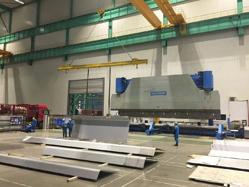
Openex is your complete machining and steel fabrication solution — a one-stop shop — for critical wind turbine parts, such as large housings, torque arms, flanges, and more. And we help you seamlessly navigate the entire process from CNC machining and welding to painting and coating.
Components we've manufactured for wind energy:
Rotor hub
Large housing
Gearboxes
Torque arms
Wind power towers
Flanges
Gears
Bearings
Other metal structures.
Contact us at sales3@openex.com.cn or call us at +86 186 5928 0806 for more information about fabrication for your projects and to receive a free project quote today.
CNC is an abbreviation of Computer Numerically Controlled. It is a new feature widely available for machine tools like lathe, milling, drilling etc. to enhance their working ability and efficiency with the aid of a computer. Till date, the working of some these machines is manually operated which give no chance for operators to rest or concentrate on other tasks. CNC machines are considered as it offered high average precision and accuracy and also time efficiency.
Today we’ll be looking at the definition, history, working principle, manufacturing process, types, as well as futures of CNC machines.
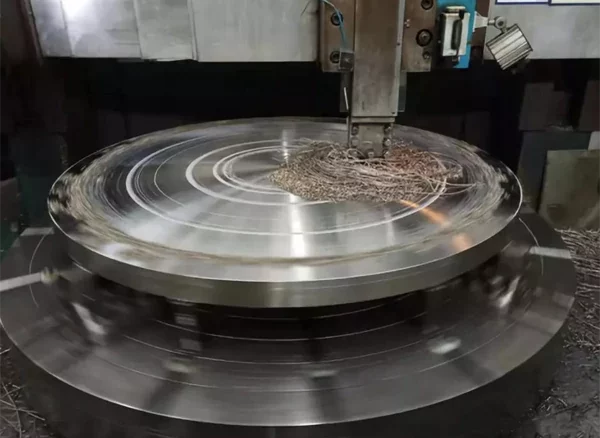
CNC or "computer numerical controlled" machines are sophisticated metalworking tools that can create complicated parts required by modern technology. Growing rapidly with the advances in computers, CNCs can be found performing work as lathes, milling machines, laser cutters, abrasive jet cutters, punch presses, press brakes, and other industrial tools. The CNC term refers to a large group of these machines that utilize computer logic to control movements and perform metalworking.
Although wood-working lathes have been in use since Biblical times, the first practical metalworking lathe was invented in 1800 by Henry Maudslay. It was simply a machine tool that held the piece of material being worked, or workpiece, in a clamp, or spindle, and rotated it so a cutting tool could machine the surface to the desired contour. The cutting tool was manipulated by the operator through the use of cranks and handwheels. Dimensional accuracy was controlled by the operator who observed the graduated dials on the handwheels and moved the cutting tool the appropriate amount. Each part that was produced required the operator to repeat the movements in the same sequence and to the same dimensions.
The first milling machine was operated in much the same manner, except the cutting tool was placed in the rotating spindle. The workpiece was mounted to the machine bed or worktable and was moved about under the cutting tool, again through the use of handwheels, to machine the workpiece contour. This early milling machine was invented by Eli Whitney in 1818.
The motions that are used in machine tools are called "axis," and are referred to as "X" (usually left to right), "Y" (usually front to back), and "Z" (up and down). The work-table may also be rotated in the horizontal or vertical plane, creating a fourth axis of motion. Some machines have a fifth axis, which allows the spindle to pivot at an angle.
One of the problems with these early machines was that they required the operator to manipulate the handwheels to make each part. Besides being monotonous and physically exhausting work, the ability of the operator to make identical parts was limited. Slight differences in operation resulted in variation of the axis dimensions, which, in turn, created poorly fitting or unusable parts. Scrap levels for the operations were high, wasting raw materials and labor time. As production quantities increased, the number of usable parts produced per operator per day were no longer economical. What was needed was a means to operate the motions of the machine automatically. Early attempts to "automate" these operations used a series of cams that moved the tools or worktable through linkages. As the cam rotated, a link followed the surface of the cam face, moving the cutting tool or the workpiece through a series of motions. The cam face was shaped to control the amount of linkage movement, and the rate at which the cam turned controlled the feedrate of the tool. These early machines were difficult to set correctly, but once set, they offered excellent repeatability for their day. Some have survived to this day and are called "Swiss" machines, a name synonymous with precision machining.
The modern CNC machine works by reading the thousands of bits of information stored in the program computer memory. To place this information in the memory, the programmer creates a series of instructions that the machine can understand. The program may consist of "code" commands, such as "M03" which instructs the controller to move the spindle to a new position, or "G99," which instructs the controller to read an auxiliary input from some process inside the machine. Code commands are the most common way to program a CNC machine tool. However, the advancement in computers has allowed the machine tool manufacturer to offer "conversational programming," where the instructions are more like plain words. In conversational programming, the "M03" command is entered simply as "MOVE," and the "G99" command is simply "READ." This type of programming allows faster training and less memorizing of the code meanings by the programmers. It is important to note, however, that most conversational machines still read code programs, since the industry relies on that form of programming quite heavily.
The controller also offers help to the programmer to speed up the machine use. In some machines, for example, the programmer can simply type in the location, diameter, and depth of a feature and the computer will select the best machining method for producing the feature in the workpiece. The latest equipment can take a computer-generated engineering model; calculate the correct tool speeds, feeds, and paths; and produce the part without a drawing or program ever being created.
The mechanical components of the machine must be rigid and strong to support the quickly moving parts. The spindle is usually the strongest part and is supported by large bearings. Whether the spindle holds the work or the tool, an automatic clamping feature allows the spindle to rapidly clamp and unclamp during the program run. A transfer arm, sometimes called the tool bar, removes a tool from the machine, places it into the magazine, selects a different tool from the magazine, and returns it to the machine through instructions in the program. Typical cycle time required for this procedure is two to eight seconds. Some machines may contain up to 400 tools in large "hives," each automatically loaded in sequence as the program runs.
The bed or worktable of the machine is supported on hardened steel "ways" which are usually protected by flexible guards.
Cast iron or Meehanite used to be the material of choice for metal working machines. Today, most machines make liberal use of weldments of hot-rolled steel and wrought products such as stainless steel to reduce cost and allow fabrication of more intricate frame designs.
Some machines are designed as cells, which means they have a specific group of parts they are designed to manufacture. Cell machines have large tool magazines to carry enough tools to do all of the various operations on each of the different parts, large worktables or the ability to change worktables, and special provisions in the controller for data inputs from other CNC machines. This allows the CNC machine to be assembled with other similarly equipped machines into a Flexible Machining Cell, which can produce more than one part simultaneously. A group of cells, some containing 20 or 30 machines, is called a Flexible Machining System. These systems can produce literally hundreds of different parts at the same time with little human intervention. Some are designed to run day and night without supervision in what is referred to as "lights out" manufacturing.
Until recently, most machining centers were built to customer specifications by the machine tool builder. Now, standardized tooling design has allowed machines to be built for stock or later sale, since the new designs can perform all the needed operations of most users. The cost of a new CNC machine runs from about $50,000 for a vertical center to $5 million for a Flexible Machining System for engine blocks. The actual manufacturing process proceeds as follows.
CNC machines are can be classified into the following types:
The future of CNC machines is exploding. One idea under development is a spider-like machine whose spindle is suspended by six telescoping ballscrew struts. The struts are like the ways in a conventional machine, but they are round with the ballscrew assembly in the center. The motions of the spindle are controlled by a sophisticated computer performing millions of calculations to assure proper part contour. Costing several million dollars to develop and using high level, proprietary mathematics, this machine promises to perform previously unheard of operations in metal machining. Advancement in computers and artificial intelligence will make CNC machines of the future faster and easier to operate. This will not come cheaply, and the price of sophisticated CNC machines will be beyond the reach of many companies. It will, how-ever, reduce the prices of the basic CNC machines performing the original three-axis movements.
Openex specializes in fabricated metal safety products and steel welding products that are built to fit your industry needs. We are a leading manufacturer of fabricated components for numerous industries including mining&engineering, oil&gas, automotive, aerospace, energy, construction, etc. With our state-of-the-art equipment and our years of experience, Openex can take your design from prototype to production in the time you need and the quality you expect.
Contact us at sales3@openex.com.cn or call us at +86 186 5928 0806 for more information about machining for your industry and to receive a free project quote today.
Gears play a prominent role in mechanical power transmission. A gear or cogwheel is a rotating machine part having cut teeth, or cogs, which mesh with another toothed part to transmit torque.
Geared devices can change the speed, torque, and direction of a power source. Gears almost always produce a change in torque, creating a mechanical advantage, through their gear ratio, and thus may be considered a simple machine. The teeth on the two meshing gears all have the same shape. Two or more meshing gears, working in a sequence, are called a gearbox.
Gears of various type, size and material are widely used in several machines from simple wall clocks and wrist watches to simple machines to complex machines and manufacturing machine tools, to automobiles, aviation, defense, to very large gear boxes are used in large ships, cranes, wind turbines, Railways, aviation, space telescopes to construction machinery, for dam gate operations and heavy weight lifting machines and systems requiring positive and stepped drive.
Gearbox is a mechanical system formed by mounting gears on a frame so the teeth of the gears engage. Gear teeth are designed to ensure the pitch circles of engaging gears roll on each other without slipping, providing a smooth transmission of rotation from one gear to the next. The speed ratio for a pair of meshing gears can be computed from ratio of the radii of the pitch circles and the ratio of the number of teeth on each gear. Friction and wear between two gears is dependent on the tooth profile. The most commonly used in modern times, is the involute profile.
Features of gears and gearbox include:
When gears are put in a frame or box, it is called Gear Box. There are several applications for witch, standard speed and power ratios are made available. The gear boxes have several purposes viz power/ torque amplifier or speed reducer where output gear has more teeth than the input gear. Conversely, if the output gear has fewer teeth than the input gear, then the gear train reduces the input torque and increases the speed of output shaft. All configurations and applications are possible for gears and gear box designs.
Gears are widely used in various mechanisms and devices to transmit power and motion positively without slip between parallel, intersecting axis and nonintersecting, non-parallel shafts, without change in the direction of rotation, with change in the direction of rotation, without change of speed of rotation, with change in speed at any desired ratio. Often some gearing system like rack – and – pinion is also used to transform rotary motion into linear motion and vice-versa.
The major applications are: Speed gear box, feed gear box and some other kinematic units of machine tools, Speed drives in all types of simple to complex manufacturing machinery, automobiles, Speed and / or feed drives of several metal forming machines, all most all industrial Machinery and appliances use gears and gear boxes. Large and heavy-duty gear boxes are used in mining, cement industries, sugar industries, cranes, conveyors etc. Precision equipment like clocks and watches and industrial robots and toys also use gears.
Gears and gearboxes are widely used in various industries from heavy machine equipment like cement, construction, mining industries, power, fertilizer, machine tools, machine products, industrial machines and equipment in food processing, pharma, dairy, etc.
With its use in assembly lines, conveyor belts, bottling, packaging, and positioning of products, wind energy to fossil fuels power plants, the demand for precision and efficient gearboxes is expected to get a boost. The automated material handling sector will witness steady growth with new equipment installation, growing production facilities, extension of plants and construction of industries. The demand from all the industrial sectors in addition to auto sector will support the growth.
The presence of substitutes such as direct drive systems may hamper the market. These products eliminate the use of gears, thus reducing the weight and complexity, and increasing the efficiency as there is no energy loss. Use of direct drives through software is limited to precise speed control applications. But this shift from gear box is hard to affect the high power/ torque products as gear box has lower overall costs then the direct drive systems. The gear products are seeing huge jump in production with 3D modeling CNC machining, grinding etc. for design and manufacture precision and custom products at low costs.
Gears and gear boxes are products that are very specialized machined component. The manufacturers of industrial machinery and all most all end user segments have to normally source these products from special gears and gear boxes manufacturing units. Even the automobile gears are supplied by specialized manufacturing units.
Geared Motors – electric motors built in with gears are emerging as new trend in this sector mostly in range of 7.5 kW to 75 KW. The largest segment of the gear motors market is 7.5 KW to 15 KW range as it has large number of applications. Most applications are in material handling, food & beverage, and automotive sectors.
Gear motors are likely to grow in demand throughout the industry for production, transportation, and processing industries. In view of the rapid growth of industrial machinery and equipment sector, there is very good scope for a gear and gear box manufacturing unit with design, and manufacturing facilities and capabilities. The new unit specializing in specific product range and customer / product group in end users will have easy and successful access to the market. Choosing niche products like geared motors for supply to customers can be very helpful.
Various grades of alloy steels are most commonly used because of their high strength-to-weight ratio and low cost. These are either cast or forged depending on end application. Gear production is done by machining of standard stock items like rods, billets. Numerous nonferrous alloys, cast irons, powder-metallurgy and even plastics are used in the manufacture of gears. The gear blanks are produced by die cast, investment casting, and powder metallurgy etc. processes. The project may select product mix and select gear blank process viz casting / forging to focus the end consumer segments.
Manufacture of gears needs several processing operations in depending upon the material and type of the gears and quality desired. The stages generally are:
Gear blanks and even gears along with teeth requiring substantial to little machining or finishing are produced by various casting processes.
It is estimated that almost 80% of all gearing produced worldwide is produced by using gear blanks cast, forged, in near final shape.
Machining:
The most common form of gear machining is cutting metal by tools called hob. The hobbing cutters rotate and mesh with gear blank like a meshing gear thereby generating teeth profile on blank. Other processes like gear shaping, milling, and broaching also exist. For metal gears in the transmissions of cars and trucks, the teeth are heat treated to make them hard and more wear resistant while leaving the core soft and tough. For large gears that are prone to warp, a quench press is used.
Finishing Processes:
Gear-tooth shaving, grinding, honing and lapping is the finishing processes that provide tooth profile correction, accurate tolerances and surface finish. Gear honing machines produce teeth to reduce the surface roughness of the tooth profile. Gears are lapped on gear-lapping machines after they have undergone heat treatment.
Quality Control:
Overall gear geometry is inspected and verified using various methods such as coordinate-measuring machines, white light scanner or laser scanning. Metal composition is testes at blank stage. Other tests like teeth skin hardness etc. are done as per requirements. Important dimensional variations of gears result from variations in the combinations of the dimensions of the tools used to manufacture them. An important parameter for meshing qualities is backlash. Precision gears are inspected by a method where meshing gear vibrations are recorded showing variations with a high resolution as the gear was rotated.
A gear is a component part of gearboxes and is characterised by teeth around a circular or cylindrical surface, commonly known as a gear blank. This article provides a basic understanding of gear box manufacture, application, industry and manufacture process of gear box.
Openex specializes in fabricated metal safety products and steel welding products that are built to fit your industry needs. We are a leading manufacturer of fabricated components for numerous industries including mining&engineering, oil&gas, automotive, aerospace, energy, construction, etc. With our state-of-the-art equipment and our years of experience, Openex can take your design from prototype to production in the time you need and the quality you expect.
Contact us at sales3@openex.com.cn or call us at +86 186 5928 0806 for more information about fabrication for your industry and to receive a free project quote today.
Sheet metal Fabrication is a value-added process that involves the creation of machines parts, panels, and structures from various steel sheet as raw materials. Sheet Metal fabrication jobs usually start with design drawings including precise measurements as per customer or product specifications. The sheets are then move to the fabrication stage where different parts of design specified are cut from sheets or punched, bent, formed, deep drawn, and finally all the parts are welded or fastened to give final products. Some of the items may be joined at installation stage of the final product / project.
Typical sheet metal fabrication projects include loose parts, structural frames for machines and equipment ranging from domestic appliances viz washing machine, refrigerator and furniture items viz stairs and hand railings fences for buildings to industrial machine panels, automobile body parts.
The global sheet metal market can be bifurcated into automobile, aerospace, building & construction for roofing/ panels etc, steel pipes and tube industries, Air-Conditioning Ducts Pipe, agricultural machinery, shipbuilding, and others machinery viz industrial, chemical, pharma, food, etc as well as in in furniture, utensils, consumer durable and electronic and computer industry, etc. The products are used in large volumes. Steel sheets of various grades, stainless steel, Aluminum and brass, copper etc sheet metals parts are being consumed in variety of equipment.
The main industries that require the sheet metal components are all types of automobiles, off road, heavy vehicles for body and other components, domestic white goods, electronics for equipment chassis, material handling and mining, electrical control panels and internal components like cable trays, rails etc., Industrial machine casings, guards, housing and construction industry, medical equipment, defense and aviation sector.
The market analysis identifies the growing demand for fabricated metal products. Though most manufacturing companies produce only a limited range of products, the requirement of fabricated metals has been considerably high in automotive and consumer durable/ appliances segments and other machinery segments.
Sheet metal can come in a wide variety of types, and fabrication can adapt the metal to whatever purposes you may need. Types of common metals used in sheet metal fabrication include:
Sheet Metal fabrication involves various processing technologies ranging from most common to advanced system depending on size, shape, other complexities, precision of components as well as volume to be produced.
Sheet metal fabrication is a process that can be performed using multiple different methods or approaches. Here are some of these methods:
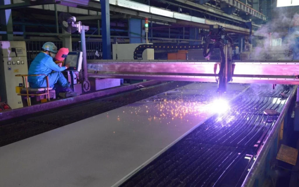 Every fabrication process begins with sheet metal cutting. The cutting method used depends on the thickness of the metal and the project’s specifications. Several ways you could cut metal for your project include:
Bending is one of the most common sheet metal fabrication operations. Also known as press braking, flanging, die bending, folding and edging, this method is used to deform a material to an angular shape.

Once you’ve cut, stretched, shrank, and welded your metal, the final basic sheet metal fabrication step is to finish your project. Adding a finish to your metal will enable it to last longer and perform better. Three common finishing techniques are:
Machining refers to the process of shaping metal by removing the unwanted material from it. This process can be performed in a variety of ways. There are many different machining processes, including drilling, turning, and milling.
Machines and Tools are Used in Sheet Metal Fabrication
Sheet metal fabrication is a very broad subject area and uses many tools, machines and joining processes. Sheet metal workers fabricate, assemble, alter and install a variety of sheet metal products. Typical jobs performed by a sheet metal worker include HVAC (Heating, Ventilation and Air Conditioning) ductwork, industrial sheet metal work and residential sheet metal work as well as aviation construction. This guide provides a basic understanding of sheet metal fabrication, metal material types, different methods, and machines used of sheet metal fabrication.
Openex specializes in fabricated metal safety products and steel welding products that are built to fit your industry needs. We are a leading manufacturer of fabricated components for numerous industries including mining&engineering, oil&gas, automotive, aerospace, energy, construction, etc. With our state-of-the-art equipment and our years of experience, Openex can take your design from prototype to production in the time you need and the quality you expect.
Contact us at sales3@openex.com.cn or call us at +86 186 5928 0806 for more information about fabrication for your industry and to receive a free project quote today.
Herewith we’d like to inform you about the successful Certificate of Registration for IATF 16949:2016 that has taken place last week.
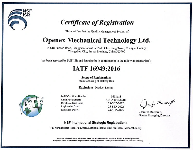
The scope of Registration is to guarantee the Manufacturing of steel components & respective processing and assemblies in compliance with the most widely used international standards in the automotive industry.
We are convinced that this certification, its defined criteria and high expectations helps us to improve our quality and service performance, through a robust quality management system.
We always emphasize the importance of providing parts with satisfying quality to our customers. we have a comprehensive range of additional capabilities, from design engineering to product assembly, finishing, and everything in between to meet the needs of your production part or project. Contact us at sales3@openex.com.cn now for more information about our CNC machining capabilities or a quote.
One of the most integral parts of the ship is its bottom structure. It is designed not only to give the hull the required strength to withstand the weight of the cargo but also to withstand the external hydrostatic loads that act on the bottom of the hull.
A ship’s hull is basically made up of bent plates welded together. If these plates are not stiffened, the bending moments on the plates due to the loads may exceed the value of stress that can be withstood by the material, and hence cause failure. So, the plates are stiffened (or their section modulus is increased) by adding stiffeners to them.
Now, there are two basic ways to stiffen a ship –
Transverse Stiffening
Longitudinal Stiffening
Transverse Stiffening or Transverse Framing: This is carried out in ships less than 120 meters in length. In transverse stiffening, the stiffeners run along with the breadth of the ship.
Longitudinal Stiffening or Longitudinal Framing: This type of framing employs stiffeners that run longitudinally, that is along the length of the ship, and is used in all seagoing ships having a length more than 120 meters.
Now that we have an idea of the two types of framing, we need to acquaint ourselves with another categorization of bottom structure framing in ships:
Usually, all smaller ships are single-bottomed, as they do not need a double bottom to withstand the load of the cargo. In these ships, the plate floors (see the figure to understand the context of ‘Floors’ in shipbuilding) themselves act as the stiffening members of the bottom shell plating. Plate floors (as shown in the figures) constitute transversely running plates at every frame spacing.
When the hydrostatic pressure under the bottom shell exerts a bending moment in the bottom shell, the plate floor takes up the bending stress.
So, designers treat all such members taking up bending stresses as beams. Empirically, the bending moment in a beam increases with the increasing span. So, what if we could reduce the span of the plate floor to further increase its stress capacity?
This is why intercostal girders are used (see the image). The number of intercostal girders would however increase with an increasing beam of the ship since that would also result in increased length of a plate floor.
A uniform wood ceiling is provided on top of all the plate floors, to provide stowage of cargo. But that doesn’t make it a double bottom structure as the wood would not take up any stresses exerted onto the bottom structure.
All seagoing ships are double-bottomed. In such a structural arrangement, a tank top is provided above the plate and bracket floors. Bracket floors are a little different from plate floors, in as much as they are not comprised of one single plate running athwartship, but only brackets at the port and starboard end, with struts that support the tank top with the bottom shell.
Bracket floors are mostly placed at each frame, and plate floors are generally placed at every three to four-frame space. The space within the double bottom (that is, between the tank top, and outer bottom shell) is used up for carrying ballast, fuel oil, dirty oil, fresh water, and other consumables.
Therefore, there're four types:
Transversely Framed, Single Bottom
Transversely Framed, Double Bottom
Longitudinally Framed, Single Bottom
Longitudinally Framed, Double Bottom
But in the fact that ships longer than 120 meters are subjected to high global longitudinal bending stresses like hogging and sagging in different load conditions, unlike smaller ships. So Longitudinally Framed Single Bottom cann't be used.
Let's learn more about the other tree structures:
-The plate floors act as transverse stiffeners, and their spans are reduced by the use of intercostal side girders that run longitudinally.
-Most single bottom ships are provided with a bar keel that extends along the length of the ship up to a certain waterline at the stem. The bar is slightly protruded outside the outer bottom shell.
-The outer bottom shell plating just adjacent to the bar keel is called Garboard strake, and its thickness is more than the thickness of the remaining bottom shell.
-All the plate floors are flanged at their tops, so as to increase their bending strength.
-Manholes are provided on the plate floors for crew access. These holes are flange too, so as to reduce stress concentration.

-This is used in ships of length less than 120 meters. (See how the length factor dominates over the type of framing used)
-The bracket floors form the transverse stiffeners at every frame, and plate floors are used at every 3 to 4 frame space, or 1.8 meters intervals.
-Similar to the single bottom, to reduce the span of the plates, intercostal side girders of keelsons are used that run longitudinally. An important thing to note is that the side girders are continuous members, that is, where there is an intersection between a plate floor and a side girder, the plate floor is cut and welded on both the sides of the girder and not the other way round. Why? Remember, we needed to reduce the span of the plate floors, hence the girders will act as supporting members to the plate floors.
-Flat plate keels are used in these structures. The keel plating thickness is a very important decision-maker in the strength of the ship. This is to be calculated from the formula dedicated to this purpose, provided by the relevant classification society.
-Intercostal girders or side girders, and plate floors will have lightning holes at regular intervals to reduce the structural weight and will have manholes (flanged) to provide access.
-Drain holes will be provided on the plate floors to help drainage of liquids. Plate floors are further stiffened by flat bar stiffeners (see image below), and bracket floors, by angle struts to prevent warping.

-The prime stiffening members are longitudinally running bulb sections or angle sections. The stiffeners on the bottom plating are called outer bottom longitudinals, and those that stiffen the tank top plating are called tank top longitudinals.
-The span of each longitudinal is equal to three of four frame spaces. That is, at each three or four frames, there would be a plate floor to support the longitudinal. A bracker floor is placed at almost every frame, but it does not support the longitudinals.
-Intercostal girders are used, as usual, to reduce the span of the plate floors.
If you notice carefully, the longitudinals run across plate floors through holes called scallops. So in a frame, where it is required to support the span of a longitudinal using a plate floor, the longitudinal is welded with a small plate to the plate floor, therefore rendering the scallop as a support end.
-In bracket floors, tank top and bottom shell longitudinals are supported to each other by means of angle struts.
-In plate floors, the longitudinals of the tank top and bottom shell are supported to each other by flat bar stiffeners, to restrict bending, torsion, and buckling.
-As usual, drain holes are used for fluid drainage and air holes are used for the passage of air. Note their positions in the images, to visualise the exact layout.
-Margin plates are used in some designs, to lead the flow of waste fluids (bilge) towards the bilge wells on either side of the ship.
-A continuous centre girder runs through the length of the ship, supporting the entire bottom structure, the keel plate, and the garboard strake.

Moreover, when one analyses the feasibility of a bottom structure, it is important to test for all possible modes and types of failure.
Openex has rich fabrication experience in shipbuilding industry. We've already offer gear case fabrication, ship bottom structure fabrication, ship bulkhead and other metal fabrication services to customers.

Contact us at bell@openex.com.cn today to learn more about our ship structure fabrication service and other services we offer.
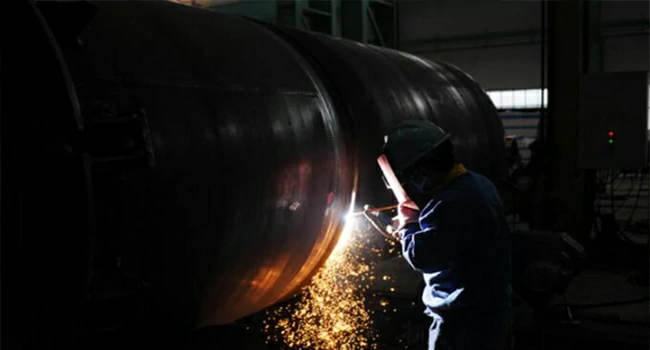
The ability to put things together to build a useful tool has been important since the dawn of humanity. Early civilizations used vines or rope to tie stones to sticks to make tools such as axes. Later, glues or cement were used to hold parts together. Forge welding (FOW) was used to join smaller pieces of metal that could be heated in a forge and hammered together. At the dawn of the Iron Age, rivets were used to fabricate large metal structures like bridges, boilers, trains, and ships. But with the advent of modern welding, cutting, and brazing, civilization began advancing more rapidly. In fact, modern civilization could not exist without welding.
Today, many things we touch were manufactured using some welding processor that was made on equipment that was welded.
The skills of welding, cutting, and brazing are an essential part of metal fabrication.
• Metal fabrication is the building, shaping, and assembling of a product, equipment, or machine from raw metal stock. Metal fabrication can be done using rivets, bolts, welding, and so forth.
• A welded metal fabrication is primarily assembled using one or more of the following processes: welding, thermal cutting, or brazing.
• A weldment is an assembly in which its component parts are all joined by welding.
In some cases, a welded fabricated part may require some post-weld finishing such as grinding, drilling, machining, or painting to complete the fabrication.
Modern welding techniques are employed in the construction of numerous products. Ships, buildings, bridges, and recreational rides are examples of welded fabrications.
The exploration of space would not be possible without modern welding techniques. From the very beginning of early rockets to today’s aerospace industry, welding has played an important role. Many aerospace welding advancements have helped improve our daily lives.
Many experiments aboard the Space Station have involved welding and metal joining. The International Space Station was constructed using many advanced welding techniques. Someday, welders will be required to build even larger structures in the vacuum of space.
Welding is used extensively in the manufacture of automobiles, farm equipment, home appliances, computer components, mining equipment, and construction equipment. Railway equipment, furnaces, boilers, air-conditioning units, and hundreds of other products we use in our daily lives are also joined together by some type of welding process.
The process of metal fabrication can be divided into several, often distinct steps. Following are the primary steps for fabrication:
• Layout—the process of drawing lines on the raw metal stock according to the parts drawings and specifications.
• Cut out—the process of removing all of the unwanted material around the laid-out part or sometimes just cutting material to the desired length. Some of the most common methods of cutting out the parts are flame cutting, plasma cutting, sawing, and punching.
• Assembling—the process of placing all the parts together in the correct location and orientation with each other. The parts may be held in place with small welds called tack welds or by some type of clamp.
• Welding—the process of permanently attaching the parts together to form the finished part.
• Finishing—can be accomplished by any number of different processes such as grinding, polishing, drilling, machining, painting, etc.
Not all metal fabrication includes all of the steps, and the difficulty of each step varies with the complexity of the fabrication. In addition, sometimes the order in which each step is done may change. For example, it may be necessary to wait until part of the assembly has been welded before laying out the location of an additional part; or a part may be trimmed to fit once other parts have been welded in place.
Openex is a professional heavy machining and large fabrication service provider. We provide a comprehensive range of custom metalworking services to customers around the globe. We not only work with all the typical metals, such as carbon steel, stainless steel, aluminum, and copper alloys, but also rare metals like nickel and titanium alloys.
Any metal fabrication requirements, feel free to contact us at bell@openex.com.cn.

Tube sheet is widely applied in the industry of heat exchanger, pressure vessel, paper machine, desalination, refinery, nuclear power, steam turbine, etc.
The biggest tube sheet we have ever made is 8720 mm in diameter. Innse three-axis deep hole drill, other four-axis and two-axis deep hole drill are the machines that work on the tube sheet.

The Coronavirus COVID-19 is spreading within 209 countries and territories as of 10 Apr 2020, and has caused almost 1.5 million people infected and 88 thousand deaths. In this global crisis moment, every one of us needs to unite together as one race, and devote each effort to fighting this unprecedented virus. The medical staff is working hard on the battlefront. Ordinary people are containing themselves at home. Many motor companies are busy in producing face masks, ventilators which are desperately needed all over the world.
We, at Openex, are also doing our own part in this battle. Our Engineer Team worked day and night for weeks and have finally completed design of an efficient N95 coded face mask machine with the highest productivity ever known, which can produce 300-400pcs masks per minute, more than 3 times faster than the popular model. We hope, by applying our machines, millions of face masks can be produced every week, delivered to the hands of everyone who has to exposed to unknown public environment, especially who are battling on the front line.
We can also supply many parts, components for mask machines, ventilators and PCR testers. No matter the parts/components are large or small, precision or not, and no matter they are made by machining, metal fabricating, or plastic injecting, we can do the jobs well and in a quick manner.
Free To contact us at bell@openex.com.cn to Get More Details

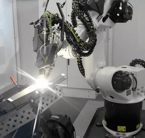
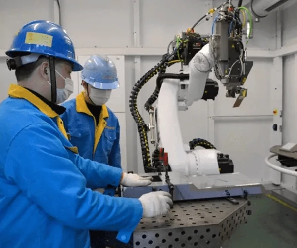
We are pleased to announce that an automatic welding unit integrated with a KUKA robot and a laser welding machine Trulaser Robot 5020 with a power 3KW has been added to our machinery array. This unit is universally suitable for welding on the following metal sheets: Stainless Steel, Carbon Steel, Aluminum, Titanium, and other known alloys. As it is equipped with a coordinated dual axial positioner and a “Teachline” automatic welding seam tracking module, this welding unit can easily weld on workpiece even with complex shape, without a stop for the workpiece to change location or angle, hence it achieves high-speed welding up to 3.5 meters/minutes in the case of 2mm sheet.
In summary, it has the following advantages:
1, The least deformation to the metal sheet thanks to its high energy density of the laser beam.
2, Universal suitable for many types of metal, even between two different metals;
3, It can do continual welding, spot welding, or stich welding;
4, Almost no dead space for the welding gun to reach;
5, High speed up to 3.5m/minute for continue welding;
6, Not much necessary for post polishing
We can expect high-quality welding with the join-in of this welding unit. If you happen to need a fabrication job done by such a nice system, please feel free to contact us at bell@openex.com.cn.